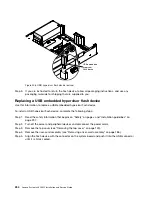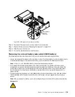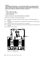
Replacing the 2.5-inch simple-swap backplate assembly/hot-swap hard
disk drive backplane
Use this information to replace the 2.5-inch simple-swap backplate assembly/hot-swap hard disk drive
backplane.
To install the 2.5-inch simple-swap backplate assembly/hot-swap hard disk drive backplane, complete the
following steps:
Step 1.
Read the safety information that begins on “Safety” on page v and “Installation guidelines” on
page 297.
Step 2.
Turn off the server, and disconnect all power cords and external cables.
Step 3.
Remove the top cover (see “Removing the top cover” on page 149).
Step 4.
Pull the hard disk drives or fillers out of the server slightly to disengage them from the backplate
assembly/backplane. See “Removing a hot-swap hard disk drive” on page 158 and “Removing a
simple-swap hard disk drive” on page 161 for details.
Step 5.
Remove the fan cage assembly (see “Removing the fan cage assembly” on page 178).
Step 6.
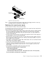
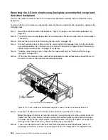
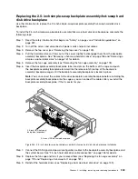
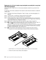
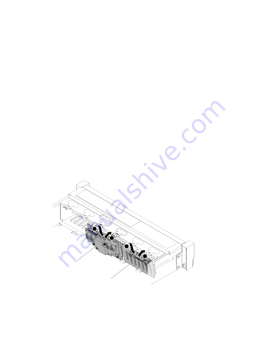
Insert the backplate assembly/backplane tabs into slots on the bottom of the cage and push
the backplate assembly/backplane forward into the release latch (on top of the backplate
assembly/backplane cage) until the backplate assembly/backplane is locked in place.
Note:
You can connect the cables to the drive backplate assembly/backplane before installing the
backplate assembly/backplane onto the cage or you can connect the cables after you install the
backplate assembly/backplane, if that is easier for you.
2.5-inch HDD hot-swap backplane
2.5-inch HDD hot-swap
backplane (expander)
2
1
1
2
Figure 203. 2.5-inch simple-swap backplate assembly/hot-swap hard disk drive backplane installation
Step 7.
Connect the SAS signal and power/configuration cables to the backplate assembly/backplane and
the system board. See “2.5-inch hard disk drive cable connection” on page 136 for details.
Step 8.
Replace the fan cage and fans if you removed them (see “Replacing the fan cage assembly” on
page 179 and “Replacing a hot-swap fan” on page 181).
Step 9.
Reinstall the hard disk drives (see “Replacing a hot-swap hard disk drive” on page 159).
Installing, removing, and replacing components
249
Содержание x3650 M5
Страница 1: ...Lenovo System x3650 M5 Installation and Service Guide Machine Type 8871 ...
Страница 47: ...Figure 35 System board switches jumpers and buttons Chapter 1 The System x3650 M5 server 35 ...
Страница 60: ...48 Lenovo System x3650 M5 Installation and Service Guide ...
Страница 80: ...68 Lenovo System x3650 M5 Installation and Service Guide ...
Страница 124: ...112 Lenovo System x3650 M5 Installation and Service Guide ...
Страница 146: ...134 Lenovo System x3650 M5 Installation and Service Guide ...
Страница 1322: ...1310 Lenovo System x3650 M5 Installation and Service Guide ...
Страница 1329: ...People s Republic of China Class A electronic emission statement Taiwan Class A compliance statement Appendix E Notices 1317 ...
Страница 1330: ...Taiwan BSMI RoHS declaration 1318 Lenovo System x3650 M5 Installation and Service Guide ...
Страница 1339: ......
Страница 1340: ......

