background image

ThinkServer TD100 and TD100x Types 6398, 6399,
6419, 6429, 4203, 4204, 4205, and 4206

Hardware Maintenance Manual

Содержание ThinkServer TD100

Страница 1: ...ThinkServer TD100 and TD100x Types 6398 6399 6419 6429 4203 4204 4205 and 4206 Hardware Maintenance Manual ...

Страница 2: ......

Страница 3: ...ThinkServer TD100 and TD100x Types 6398 6399 6419 6429 4203 4204 4205 and 4206 Hardware Maintenance Manual ...

Страница 4: ...008 LENOVO products data computer software and services have been developed exclusively at private expense and are sold to governmental entities as commercial items as defined by 48 C F R 2 101 with limited and restricted rights to use reproduction and disclosure LIMITED AND RESTRICTED RIGHTS NOTICE If products data computer software or services are delivered pursuant a General Services Administra...

Страница 5: ...n Setup Utility program 16 Using the RAID configuration programs 16 Using RAID Manager 20 Using the ThinkServer EasyStartup program 22 Using the Boot Menu program 23 Enabling the Broadcom Gigabit Ethernet Utility program 23 Configuring the Ethernet controller 23 Chapter 3 Parts listing TD100 Types 6398 6399 6419 6429 4203 and 4206 25 Replaceable server components 26 Power cords 61 Chapter 4 Removi...

Страница 6: ...he control panel assembly 124 Removing and replacing FRUs 125 Removing the hot swap power supply cage assembly 125 Installing the hot swap power supply cage assembly 127 Removing the simple swap backplate TD100 some models 128 Installing the simple swap backplate TD100 some models 130 Removing the SAS SATA backplane 131 Installing the SAS SATA backplane 132 Removing a non hot swap power supply cag...

Страница 7: ...ems 213 Solving power problems 213 Solving Ethernet controller problems 214 Solving undetermined problems 215 Calling Lenovo for service 216 Getting help and technical assistance 217 Before you call 217 Using the documentation 217 Getting help and information from the World Wide Web 217 Calling for service 218 Using other services 218 Purchasing additional services 219 Lenovo Taiwan product servic...

Страница 8: ...Taiwanese Class A warning statement 228 Chinese Class A warning statement 228 Korean Class A warning statement 228 Index 229 vi ThinkServer TD100 and TD100x Hardware Maintenance Manual ...

Страница 9: ...tteen lue turvaohjeet kohdasta Safety Information Avant d installer ce produit lisez les consignes de sécurité Vor der Installation dieses Produkts die Sicherheitshinweise lesen Prima di installare questo prodotto leggere le Informazioni sulla Sicurezza Les sikkerhetsinformasjonen Safety Information før du installerer dette produktet Antes de instalar este produto leia as Informações sobre Seguran...

Страница 10: ...ds such as a damaged CRT face or a bulging or leaking capacitor v Mechanical hazards such as loose or missing hardware To inspect the product for potential unsafe conditions complete the following steps 1 Make sure that the power is off and the power cord is disconnected 2 Make sure that the exterior cover is not damaged loose or broken and observe any sharp edges 3 Check the power cord v Make sur...

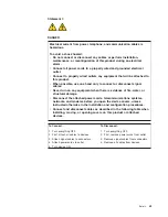
Страница 11: ...echanical inspection work near power supplies or remove or install main units v Before you work on the equipment disconnect the power cord If you cannot disconnect the power cord have the customer power off the wall box that supplies power to the equipment and lock the wall box in the off position v Never assume that power has been disconnected from a circuit Check it to make sure that it has been...

Страница 12: ...ety Information document For example if a caution statement begins with a number 1 translations for that caution statement appear in the Safety Information document under statement 1 Be sure to read all caution and danger statements in this documentation before performing the instructions Read any additional safety information that comes with your server or optional device before you install the d...

Страница 13: ...equipment when there is evidence of fire water or structural damage v Disconnect the attached power cords telecommunications systems networks and modems before you open the device covers unless instructed otherwise in the installation and configuration procedures v Connect and disconnect cables as described in the following table when installing moving or opening covers on this product or attached...

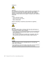
Страница 14: ...er products such as CD drives DVD drives fiber optic devices or transmitters are installed note the following v Do not remove the covers Removing the covers of the laser product could result in exposure to hazardous laser radiation There are no serviceable parts inside the device v Use of controls or adjustments or performance of procedures other than those specified herein might result in hazardo...

Страница 15: ...power control button on the device and the power switch on the power supply do not turn off the electrical current supplied to the device The device also might have more than one power cord To remove all electrical current from the device ensure that all power cords are disconnected from the power source 1 2 Safety xiii ...

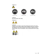
Страница 16: ...t inside any component that has this label attached There are no serviceable parts inside these components If you suspect a problem with one of these parts contact a service technician Statement 10 CAUTION Do not place any object weighing more than 82 kg 180 lb on top of rack mounted devices 82 kg 180 lb xiv ThinkServer TD100 and TD100x Hardware Maintenance Manual ...

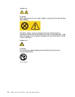
Страница 17: ...Statement 11 CAUTION The following label indicates sharp edges corners or joints nearby Statement 17 CAUTION The following label indicates moving parts nearby Safety xv ...

Страница 18: ...xvi ThinkServer TD100 and TD100x Hardware Maintenance Manual ...

Страница 19: ...stalling some optional devices v User Guide This PDF is available on the ThinkServer Documentation DVD It provides general information about the server including information about features and how to configure the server It also contains detailed instructions for installing removing and connecting optional devices that the server supports v Rack Installation Instructions This PDF is available on t...

Страница 20: ...t is numbered for reference to the corresponding statement in the Safety Information document The following notices and statements are used in this document v Note These notices provide important tips guidance or advice v Important These notices provide information or advice that might help you avoid inconvenient or problem situations v Attention These notices indicate potential damage to programs...

Страница 21: ...agement controller BMC or onboard service processor v Broadcom 5721 10 100 1000 Ethernet controller on the system board with RJ 45 Ethernet port v Six port Serial ATA controller v Integrated RAID capability SATA HostRAID v Remote Supervisor Adapter II SlimLine v Two serial ports v One parallel port v Four Universal Serial Bus USB v2 0 ports two on front and two on rear v Keyboard port v Mouse port...

Страница 22: ...s and connectors on the front of the hot swap server models 1 System power LED 6 CD eject or DVD eject button 2 Power control button 7 Hot swap hard disk drive status LED amber 3 Hard disk drive activity LED 8 Hot swap hard disk drive activity LED green 4 System error LED 9 CD or DVD drive activity LED green 5 USB connectors 10 Front information panel 4 ThinkServer TD100 and TD100x Hardware Mainte...

Страница 23: ... it indicates that ac power is not present or the power supply or the LED itself has failed Note If this LED is off it does not mean that there is no electrical power in the server The LED might be burned out To remove all electrical power from the server you must disconnect the power cords from the electrical outlets Power control button Press this button to turn the server on and off manually Ha...

Страница 24: ...sk drive activity LED some models On some server models each hot swap drive has a hard disk drive activity LED When this green LED is flashing it indicates that the drive is in use When the drive is removed this LED also is visible on the SAS backplane next to the drive connector The backplane is the printed circuit board behind drive bays 4 through 11 Hot swap hard disk drive status LED some mode...

Страница 25: ...AC power LEDs 9 USB connectors 3 and 4 3 DC power LEDs 10 RJ45 Ethernet 10 100 1000 4 Mouse connector 11 RJ45 Ethernet 10 100 for Remote Supervisor Adapter II SlimLine 5 Keyboard connector 12 NMI button 6 Serial 1 COM 1 connector 13 Serial 2 COM 2 connector 7 Parallel connector The following illustration shows the connectors on the rear of the non hot swap power supply models Chapter 1 Introductio...

Страница 26: ... power LED This green LED provides status information about the power supply During typical operation both the ac and dc power LEDs are lit DC power LED This green LED provides status information about the power supply During typical operation both the ac and dc power LEDs are lit Mouse connector Connect a mouse device to this connector Keyboard connector Connect a PS 2 keyboard to this connector ...

Страница 27: ...mit receive activity LED This LED is on the Ethernet connector When this LED is lit it indicates that there is activity between the server and the network Ethernet link status LED This LED is on the Ethernet connector When this LED is lit it indicates that there is an active connection on the Ethernet port Remote Supervisor Adapter II SlimLine connector Connect the optional Remote Supervisor Adapt...

Страница 28: ...tration shows the internal connectors on the system board 1 2 3 4 5 6 7 8 9 10 11 12 DIMM LEDs 1 Main power 10 SAS SATA backplane power 2 Power 11 Simple swap SATA backplate 3 Power 12 Hot swap SAS SATA signal 4 USB tape 13 Hot swap main fan 5 Front panel 14 Hot swap fan redundant 6 Primary IDE 15 Battery 7 Front USB 16 Wake on LAN 8 Microprocessor 1 17 COM 2 header 9 Microprocessor 2 18 Rear fan ...

Страница 29: ...tput I O connectors on the system board 1 2 3 4 5 6 7 8 9 10 11 12 DIMM LEDs 1 Mouse 6 USB 2 2 Keyboard 7 RJ45 Ethernet 10 100 1000 3 Serial 1 COM 1 8 RJ45 Ethernet 10 100 for Remote Supervisor Adapter II SlimLine 4 Parallel 9 NMI button 5 Video 10 Serial 2 COM 2 Chapter 1 Introduction 11 ...

Страница 30: ...ons 1 2 3 4 5 6 7 8 9 10 11 12 DIMM LEDs 1 DIMM 6 7 PCI 32 bit 33 MHz 2 Microprocessor 1 8 PCI X 64 bit 133 MHz 3 Microprocessor 2 9 PCI Express x8 x8 4 VRM 10 PCI Express x8 x4 5 Battery 11 Remote Supervisor Adapter II SlimLine 6 ServeRAID adapter 12 DIMM 6 12 ThinkServer TD100 and TD100x Hardware Maintenance Manual ...

Страница 31: ...s on the system board 1 2 3 4 5 6 7 8 9 10 11 12 DIMM LEDs 1 Microprocessor error LED 2 5 ServeRAID error LED 2 VRM error LED 6 Error LED 6 3 Battery LED 7 Microprocessor mismatch LED 4 BMC heartbeat LED 8 DIMM error LEDs 1 through 12 Chapter 1 Introduction 13 ...

Страница 32: ... block v When this switch is on 1 this is normal mode v When this switch is toggled to On this enables the system to recover if the BIOS code becomes damaged See Recovering from a BIOS update failure on page 203 for more information 2 Clear CMOS v When this switch is on 2 this keeps the CMOS data This is normal mode v When this switch is toggled to On this clears the CMOS data which clears the pow...

Страница 33: ...llation tools that are specifically designed for the server The EasyStartup program simplifies the process of installing the operating system and device drivers See Using the ThinkServer EasyStartup program on page 22 for more information In addition to the EasyStartup program you can use the following configuration programs to customize the server hardware v Configuration Setup Utility program v ...

Страница 34: ...ID Configuration Utility program and ServeRAID Manager to configure and manage redundant array of independent disks RAID Be sure to use these programs as described in this document The ServeRAID 8k l SAS Controller that comes with the TD100 server hot swap SAS and hot swap SATA models enables you to configure multiple physical SAS or SATA hard disk drives to operate as logical drives in a disk arr...

Страница 35: ... and data rates v To update the firmware and BIOS code for an optional ServeRAID controller you must use the IBM ServeRAID Support CD that comes with the ServeRAID option v If you install a different type of RAID controller in the server use the method that is described in the instructions that come with the controller to view or change settings for attached devices Configuring hot swap SAS hot sw...

Страница 36: ...select the two drives that you want to group into the array 4 When you are prompted to select the RAID type select RAID 0 or RAID 1 5 Optional Type an identifier for the array 6 When you are prompted for the array build method select Quick Init 7 Follow the instructions on the screen to complete the configuration then select Done to exit 8 Restart the server Viewing the array configuration To view...

Страница 37: ... Adaptec RAID Configuration Utility menu choices The following choices are on the Adaptec RAID Configuration Utility menu v Array Configuration Utility Select this choice to create manage or delete arrays add or delete a hot spare drive or initialize drives v SerialSelect Utility Select this choice to configure the controller interface definitions or to configure the physical transfer and SATA add...

Страница 38: ...rveRAID Manager Application CD to perform the following tasks v Configure a redundant array of independent disks RAID array v Restore a SAS or SATA hard disk drive to the factory default settings erasing all data from the disk v View the RAID configuration and associated devices v Monitor the operation of the RAID controllers To perform some tasks you can run ServeRAID Manager as an installed prog...

Страница 39: ...y arrays or Modify logical drives Note Some operating systems have size limitations for logical drives Before you save the configuration make sure that the size of the logical drive is appropriate for your operating system 5 Click Apply when you are asked whether you want to apply the new configuration click Yes The configuration is saved in the controller and in the physical drives 6 Exit from Se...

Страница 40: ... notes to help you determine what server configurations and operating systems are supported by that specific version of the program The ThinkServer EasyStartup program also enables you to save the response file on a USB device or diskette for reuse and an option that enables you to install an operating systems using the saved response This option is useful if you intend to install the same operati...

Страница 41: ...rnet Utility program complete the following steps 1 Turn on the server 2 When the prompt Press F1 for Configuration Setup appears during startup press F1 3 From the Configuration Setup Utility main menu select Devices and I O Ports and press Enter 4 Select Planar Ethernet and use the Right Arrow key to set it to Enabled 5 Select Save Settings and press Enter Configuring the Ethernet controller The...

Страница 42: ...24 ThinkServer TD100 and TD100x Hardware Maintenance Manual ...

Страница 43: ...206 servers To check for an updated parts listing on the Web complete the following steps 1 Go to http www lenovo com support 2 Enter your product number machine type and model number or select Servers from the Select your product list 3 Select Servers from the Brand list 4 From Family list select ThinkServer TD100 and TD100x and click Continue Lenovo 2008 Portions IBM Corp 2008 25 ...

Страница 44: ... 11G 45J9632 1 Hard disk drive 250GB 7200 RPM 3 5 inch Simple Swap SATA II models 45J9634 1 Hard disk drive 160GB 7200 RPM 3 5 inch Hot Swap SATA II models 11G 45J9640 1 Hard disk drive 250GB 7200 RPM 3 5 inch Hot Swap SATA II models 45J9642 1 Hard disk drive 500GB 7200 RPM 3 5 inch Hot Swap SATA II models 45J9644 1 Hard disk drive 750GB 7200 RPM 3 5 inch Hot Swap SATA II models 46J9646 1 Hard dis...

Страница 45: ...er top v 5 25 inch EMC flange tower bottom 39Y8355 8 SATA hard disk drive backplane all models 41Y9078 8 SAS hard disk drive backplane all models 39Y9757 9 Back plate with cable assembly all models 41Y9078 10 Fan Cage and Card all models 41Y9067 11 Fan 120 X 38mm all models 41Y9028 12 Microprocessor duct all models 39Y8501 13 System board with tray models 11G 14U 14G 14A 12 13G 44R5619 14 Adaptec ...

Страница 46: ...3W5183 20 Microprocessor Intel Xeon X5355 Quad Core 2 66 GHz 1333 MHz 2x 4 MB L2 cache models 43W5184 20 Microprocessor Intel Xeon E5405 Quad Core 2 00 GHz 1333 MHz 12 MB L2 cache Processor models 44R5644 20 Microprocessor Intel Xeon E5410 Quad Core 2 33 GHz 1333 MHz 12 MB L2 cache Processor models 12G 13G 14G 44R5645 20 Microprocessor Intel Xeon E5420 Quad Core 2 50 GHz 1333 MHz 12 MB L2 cache Pr...

Страница 47: ...41Y9069 Side top cover all models 39Y8360 Alcohol wipe all models 59P4739 Adapter NetXtreme 1000 T Ethernet adapter all models 39Y6081 Adapter NetXtreme 1000 SX Fiber Ethernet adapter all models 39Y6090 Adapter NetXtreme 1000 TxG Dual Port Ethernet adapter all models 39Y6095 Adapter NetXtreme 1000 Express G Ethernet adapter all models 39Y6100 PRO 1000GTSV all models 39Y6107 Qlogic ISCSI single por...

Страница 48: ...r DP all models 73P5109 PRO 1000 GT server ethernet adapter QP all models 73P5209 Rack bezel assembly all models 41Y9072 SCSI adapter all models 39R8750 PCIe 8s SAS controller all models 39R8785 SAS Card all models 25R8071 Shield system board I O all models 41Y9076 Shield Kit all models 41Y9070 Slide kit all models 40K6679 RSA Slimline bracket all models 41Y9086 iSCSI SX server adapter all models ...

Страница 49: ...it CGRID 20 pins all models 44E4042 RSA SlimLine all models 44T1412 Hard drive backplane all models 46C6425 Service Label all models 39Y8356 Planar Tray all models 41Y9077 Keyboard Preferred Pro w 2m cable Full Width Black USB all models 42C0060 Keyboard China all models 42C0067 Keyboard Japanese all models 42C0081 Keyboard USEng103P models 41A5100 Mouse Opt Wheel USB models 41U3013 Chapter 3 Part...

Страница 50: ...dels 45J9652 1 Hard disk drive 73GB 10K 2 5 inch Hot Swap SAS models 45J9654 1 Hard disk drive 146GB 15K 3 5 inch Hot Swap SAS models 45J9658 1 Hard disk drive 300GB 15K 3 5 inch Hot Swap SAS models 45J9660 1 Hard disk drive 500GB 7200 RPM 3 5 inch Simple Swap SATA II models 46U1024 1 Hard disk drive 450GB 15K SAS 3 5 HS HDD all models 46U2108 2 Filler Bezel all models 41Y9071 3 Filler HDD all mod...

Страница 51: ...13M 13A 13Q 13T 13H 13K 13R 13E 13J 14U 14F 14S 14L 14D 14Y 14G 14M 14A 14Q 14T 14K 14R 14E 14J 15U 15F 15S 15L 15D 15Y 11G 12G 44R5619 14 Adaptec 8K adapter with Battery KEYBISCAYNE Raid Card all models 25R8076 16 Side cover assembly with latch and bezel lock all models 39Y8362 17 Diagnostic panel kit contains all models v Blank label v Diagnostics label v Guide rail assembly v Power button v RAI...

Страница 52: ... 14A 14Q 14T 14K 14R 14E 14J 15U 15F 15S 15L 15D 15Y 44R5644 20 Microprocessor Intel Xeon E5410 Quad Core 2 33 GHz 1333 MHz 12 MB L2 cache Processor models 44R5645 20 Microprocessor Intel Xeon E5420 Quad Core 2 50 GHz 1333 MHz 12 MB L2 cache Processor models 44R5646 20 Microprocessor Intel Xeon E5430 Quad Core 2 66 GHz 1333 MHz 12 MB L2 cache Processor models 44R5647 20 Microprocessor Intel Xeon E...

Страница 53: ...14R 14E 14J 15U 15F 15S 15L 15D 15Y 11G 12G 39M3517 30 Half High Combo drive models 13G 13M 13A 13Q 13T 13H 13K 13R 13E 13J 14U 14F 14S 14L 14D 14Y 14G 14M 14A 14Q 14T 14K 14R 14E 14J 15U 15F 15S 15L 15D 15Y 11G 12G 43W4575 30 Half High Multi Burner HH Rambo 9 models 43W4577 Cover Button all models 41Y9069 Side top cover all models 39Y8360 Alcohol wipe all models 59P4739 Adapter NetXtreme 1000 T E...

Страница 54: ...PRO 1000 GT server ethernet adapter DP all models 73P5109 PRO 1000 GT server ethernet adapter QP all models 73P5209 Rack bezel assembly all models 41Y9072 SCSI adapter all models 39R8750 SAS Card all models 25R8071 Shield system board I O all models 41Y9076 Shield kit all models 41Y9070 Slide kit all models 40K6679 RSA Slimline bracket all models 41Y9086 iSCSI SX server adapter all models 30R5509 ...

Страница 55: ...r microfit CGRID 20 pins CGRID CABLE 20 all models 44E4042 RSA SlimLine all models 44T1412 Hard drive backplane all models 43X0334 Hard drive backplane all models 46C6425 VRM 11 all models 24R2694 Diag Panel Asm all models 39Y7125 PSU INTERPOSER all models 39Y8356 Planar Tray all models 41Y9077 Keyboard Preferred Pro with 2m cable Full Width Black USB all models 42C0060 Keyboard China all models 4...

Страница 56: ...4E 14J 45J9652 1 Hard disk drive 73GB 10K 2 5 inch Hot Swap SAS models 45J9654 1 Hard disk drive 146GB 15K 3 5 inch Hot Swap SAS models 13U 13F 13S 13L 13D 13Y 13G 13B 13H 13V 14M 14A 14Q 14T 14K 14R 14E 14J 45J9658 1 Hard disk drive 300GB 15K 3 5 inch Hot Swap SAS models 45J9660 1 Hard disk drive 500GB 7200 RPM 3 5 inch Simple Swap SATA II models 46U1024 1 Hard disk drive 450GB 15K SAS 3 5 HS all...

Страница 57: ...5M 15A 15Q 15T 15K 15R 15E 15J 11U 11F 11S 11L 11D 11Y 11G 11B 11H 11V 12M 12A 12Q 12T 12K 12R 12E 12J 13U 13F 13S 13L 13D 13Y 13G 13B 13H 13V 14M 14A 14Q 14T 14K 14R 14E 14J 44R5619 14 Adaptec 8K adapter with Battery KEYBISCAYNE Raid Card all models 25R8076 16 Side cover assembly with latch and bezel lock all models 39Y8362 17 Diagnostic panel kit contains all models v Blank label v Diagnostics l...

Страница 58: ... 1333 MHz 12 MB L2 cache Processor models 44R5644 20 Microprocessor Intel Xeon E5410 Quad Core 2 33 GHz 1333 MHz 12 MB L2 cache Processor models 15U 15F 15S 15L 15D 15Y 15M 15A 15Q 15T 15K 15R 15E 15J 44R5645 20 Microprocessor Intel Xeon E5420 Quad Core 2 50 GHz 1333 MHz 12 MB L2 cache Processor models 44R5646 20 Microprocessor Intel Xeon E5430 Quad Core 2 66 GHz 1333 MHz 12 MB L2 cache Processor ...

Страница 59: ...14R 14E 14J 39M3569 30 16 48X BLACK DVD ROM models 15U 15F 15S 15L 15D 15Y 15M 15A 15Q 15T 15K 15R 15E 15J 11U 11F 11S 11L 11D 11Y 11G 11B 11H 11V 12M 12A 12Q 12T 12K 12R 12E 12J 13U 13F 13S 13L 13D 13Y 13G 13B 13H 13V 14M 14A 14Q 14T 14K 14R 14E 14J 39M3517 30 Half High Combo drive models 15U 15F 15S 15L 15D 15Y 15M 15A 15Q 15T 15K 15R 15E 15J 11U 11F 11S 11L 11D 11Y 11G 11B 11H 11V 12M 12A 12Q 1...

Страница 60: ...pter all models 30R5209 Feet system all models 13N2985 Keylock with alike keys all models 26K7363 Keylock with random keys all models 26K7364 PRO 1000 GT server ethernet adapter DP all models 73P5109 PRO 1000 GT server ethernet adapter QP all models 73P5209 Rack bezel assembly all models 41Y9072 Shield system board I O all models 41Y9076 Shield kit all models 41Y9070 Slide kit all models 40K6679 R...

Страница 61: ...ll models 43X0334 Hard drive backplane all models 46C6425 MS SW Pack all models 43X1420 HDD INNER CAGE all models 44E4036 HDD OUTER CAGE all models 44E4038 CGRID CABLE 24 all models 44E4040 CGRID CABLE 20 all models 44E4042 RSA SlimLine all models 44T1412 VRM 11 all models 24R2694 10A C13 to CEE 7 7 2 8M Power Cord Fig 18 2 8M all models 39M5123 Diag Panel Asm all models 39Y7125 PSU INTERPOSER all...

Страница 62: ... 11G 45J9652 1 Hard disk drive 73GB 10K 2 5 inch Hot Swap SAS models 45J9654 1 Hard disk drive 146GB 15K 3 5 inch Hot Swap SAS models 11G 45J9658 1 Hard disk drive 300GB 15K 3 5 inch Hot Swap SAS models 45J9660 1 Hard disk drive 500GB 7200 RPM 3 5 inch Simple Swap SATA II models 46U1024 1 Hard disk drive 450GB 15K SAS 3 5 HS HDD all models 46U2108 2 Filler Bezel all models 41Y9071 3 Filler HDD all...

Страница 63: ...5U 15F 15S 15L 15D 15Y 15G 15M 15A 15Q 15T 15H 15K 15R 15E 15J 16U 16F 16K 16J 16S 16L 16D 16Y 16G 16M 16A 16Q 16T 16H 16R 16E 17U 17S 17L 17D 17Y 17G 17M 17A 17Q 17T 17H 17R 17E 18U 18S 18L 18D 18Y 18G 18M 18A 18Q 18T 18H 18R 18E 19G 19M 19A 19Q 19T 19K 19J 11G 12U 12F 12S 12L 12D 12Y 12G 12M 12A 12Q 12T 12B 12H 12V 12K 12R 12E 12J 13U 13F 13S 13L 13D 13Y 13G 13M 13A 13Q 13T 13B 13H 13V 13K 13R 1...

Страница 64: ...e 2 33 GHz 1333 MHz 2x 4 MB L2 cache models 43W5183 20 Microprocessor Intel Xeon X5355 Quad Core 2 66 GHz 1333 MHz 2x 4 MB L2 cache models 43W5184 20 Microprocessor Intel Xeon E5405 Quad Core 2 00 GHz 1333 MHz 12 MB L2 cache Processor models 44R5644 20 Microprocessor Intel Xeon E5410 Quad Core 2 33 GHz 1333 MHz 12 MB L2 cache Processor models 15U 15F 15S 15L 15D 15Y 15G 15M 15A 15Q 15T 15H 15K 15R...

Страница 65: ...T 12B 12H 12V 12K 12R 12E 12J 13U 13F 13S 13L 13D 13Y 13G 13M 13A 13Q 13T 13B 13H 13V 13K 13R 13E 13J 24R2694 27 Power supply 835 W models 14G 14U 14F 14S 14L 14D 14Y 14G 14M 14A 14Q 14T 14H 14K 14R 14E 14J 15U 15F 15S 15L 15D 15Y 15G 15M 15A 15Q 15T 15H 15K 15R 15E 15J 16U 16F 16K 16J 16S 16L 16D 16Y 16G 16M 16A 16Q 16T 16H 16R 16E 17U 17S 17L 17D 17Y 17G 17M 17A 17Q 17T 17H 17R 17E 18U 18S 18L 1...

Страница 66: ...odels 39Y6095 Adapter NetXtreme 1000 Express G Ethernet adapter all models 39Y6100 Battery all models 25R8118 Cover Hard drive filler all models 41Y9043 Blower DIMM blocker all models 41Y9081 Cable SFF SAS CABLE all models 44E4044 diskette drive interposer all models 39R9343 Cable DVD signal IDE all models 13N2466 fan harness all models 39Y8341 Cable power LED all models 41Y9082 Cable SAS power al...

Страница 67: ...models 41Y9086 PCIe 8s SAS controller MARAUDER CARD all models 39R8785 PRO 1000 GTSV all models 39Y6107 Qlogic ISCSI single port PCI E adapter all models 39Y6148 DD S 5 tape drive all models 40K2553 Operator information panel assembly all models 41Y9080 Qlogic ISCSI dual port PCI E adapter all models 42C1772 3U SCSI adapter all models 43W4325 Hard drive backplane all models 43X0334 MS SW Pack all ...

Страница 68: ...art number Optional service FRU part number Keyboard Preferred Pro with 2m cable Full Width Black USB all models 42C0060 Keyboard China all models 42C0067 Keyboard Japanese all models 42C0081 Keyboard USEng103P models 41A5100 Mouse Opt Wheel USB models 41U3013 50 ThinkServer TD100 and TD100x Hardware Maintenance Manual ...

Страница 69: ...black models 39M3511 5 16 48XHLDS DVD ROM models 39M3515 5 HLDS 16 48X H H DVD ROM models 39M3569 5 16 48X BLACK DVD ROM models 39M3517 5 Half High Combo drive models 43W4575 5 Half High Multi Burner HH Rambo 9 models 43W4577 6 Hard disk drive 160GB 7200 RPM 3 5 Simple Swap SATA II models 45J9632 6 Hard disk drive 250GB 7200 RPM 3 5 Simple Swap SATA II models 45J9634 6 Hard disk drive 160GB 7200 R...

Страница 70: ...Card all models 41Y9067 11 Fan 120 X 38mm all models 41Y9028 12 Microprocessor duct all models 39Y8501 13 System board models 11U 11G 11A 44R5619 13 Tray system board all models 41Y9077 14 Adaptec 8K adapter with Battery KEYBISCAYNE Raid Card all models 25R8076 16 Easy LED Diagnostics panel assembly all models 41Y9079 17 SIDE COVER ASM all models 39Y8362 18 Blank Filler all models 39M6800 19 Heat ...

Страница 71: ...ntel Xeon E5420 Quad Core 2 50 GHz 1333 MHz 12 MB L2 cache Processor models 44R5646 20 Microprocessor Intel Xeon E5430 Quad Core 2 66 GHz 1333 MHz 12 MB L2 cache Processor models 44R5647 20 Microprocessor Intel Xeon E5440 Quad Core 2 83 GHz 1333 MHz 12 MB L2 cache Processor models 44R5648 20 Microprocessor Intel Xeon X5450 Quad Core 3 00 GHz 1333 MHz 12 MB L2 cache Processor 120 W models 44E5117 2...

Страница 72: ...all models 42C1053 Cable SFF SAS all models 44E4044 Cable SCSI all models 25R0048 Cable 390mm SAS Signal all models 42C2378 Cable Power LED all models 41Y9082 DD S 5 drive all models 40K2553 Slide Kit all models 40K6679 Cooling duct all models 39Y8504 Feet System all models 26K7345 Filler bezel assembly all models 41Y9071 Feet system all models 13N2985 Keylock with alike keys all models 26K7363 Ke...

Страница 73: ...drive backplane all models 46C6425 VRM 11 all models 24R2694 10A C13 to CEE 7 7 2 8M Power Cord Fig 18 2 8M all models 39M5123 SAS Card all models 25R8071 8i SAS BATTERY all models 25R8118 Filler HDD all models 26K8680 SCSI adapter all models 39R8750 PRO 1000GTSV all models 39Y6107 Diag Panel Asm all models 39Y7125 SAS Backplane all models 39Y9757 MS SW Pack all models 43X1420 HDD INNER CAGE all m...

Страница 74: ...W4575 5 Half High Multi Burner HH Rambo 9 models 43W4577 6 Hard disk drive 160GB 7200 RPM 3 5 Simple Swap SATA II models 45J9632 6 Hard disk drive 250GB 7200 RPM 3 5 Simple Swap SATA II models 45J9634 6 Hard disk drive 160GB 7200 RPM 3 5 inch Hot Swap SATA II models 45J9640 6 Hard disk drive 250GB 7200 RPM 3 5 inch Hot Swap SATA II models 45J9642 6 Hard disk drive 500GB 7200 RPM 3 5 inch Hot Swap ...

Страница 75: ...x 2 MB L2 cache models 41Y4276 20 Microprocessor Intel Xeon 5130 Dual Core 2 0 GHz 1333 MHz 2x 2 MB L2 cache models 41Y4277 20 Microprocessor Intel Xeon 5140 Dual Core 2 33 GHz 1333 MHz 2x 2 MB L2 cache models 41Y4278 20 Microprocessor Intel Xeon 5150 Dual Core 2 66 GHz 1333 MHz 2x 2 MB L2 cache models 41Y4279 20 Microprocessor Intel Xeon 5160 Dual Core 3 0 GHz 1333 MHz 2x 2 MB L2 cache models 41Y...

Страница 76: ...GB PC2 5300 CL5 ECC DDR2 Chipkill FBDIMM 667MHz models 46U1017 22 Memory 2GB PC2 5300 CL5 ECC DDR2 Chipkill FBDIMM 667MHz models 14U 14F 14S 14L 14D 14Y 14G 14M 14A 14Q 14T 14K 14R 14E 14J 11G 12U 12F 12S 12L 12D 12Y 12G 12B 12H 12V 13G 46U1018 22 Memory 4GB PC2 5300 CL5 ECC DDR2 Chipkill FBDIMM 667MHz models 46U1019 23 Remote Supervisor Adapter II SlimLine Bracket all models 41Y9086 24 DIMM duct ...

Страница 77: ...lock with random keys all models 26K7364 PRO 1000 GT server Ethernet adapter DP all models 73P5109 PRO 1000 GT server Ethernet adapter QP all models 73P5209 Rack bezel assembly all models 41Y9072 Shield system board I O all models 41Y9076 Shield kit all models 41Y9070 Service Label all models 39Y8359 Fan rear bracket assembly all models 41Y9074 Thermal grease all models 41Y9292 Remote Supervisor A...

Страница 78: ...CSI adapter all models 39R8750 PRO 1000GTSV all models 39Y6107 Diag Panel Asm all models 39Y7125 SAS Backplane all models 39Y9757 MS SW Pack all models 43X1420 HDD INNER CAGE all models 44E4036 HDD OUTER CAGE all models 44E4038 power microfit CGRID 24 pins CGRID CABLE 24 all models 44E4040 power microfit CGRID 20 pins CGRID CABLE 20 all models 44E4042 Keyboard Preferred Pro with 2m cable Full Widt...

Страница 79: ...Power cords Type 4203 Lenovo Power cord part number Used in these countries and regions 39M5247 Taiwan models 39M5206 China models 39M5102 Australia Fiji Kiribati Nauru New Zealand Papua New Guinea models 39M5123 Afghanistan Albania Algeria Andorra Angola Armenia Austria Azerbaijan Belarus Belgium Benin Bosnia and Herzegovina Bulgaria Burkina Faso Burundi Cambodia Cameroon Cape Verde Central Afric...

Страница 80: ...20 240 V Antigua and Barbuda Aruba Bahamas Barbados Belize Bermuda Bolivia Caicos Islands Canada Cayman Islands Colombia Costa Rica Cuba Dominican Republic Ecuador El Salvador Guam Guatemala Haiti Honduras Jamaica Mexico Micronesia Federal States of Netherlands Antilles Nicaragua Panama Peru Philippines Saudi Arabia Thailand Taiwan United States of America Venezuela models 39M5081 110 120 V Antigu...

Страница 81: ...hiti Togo Tunisia Turkey Turkmenistan Ukraine Upper Volta Uzbekistan Vanuatu Vietnam Wallis and Futuna Yugoslavia Federal Republic of Zaire models 14G 11G 13G 39M5130 Denmark models 14G 11G 13G 39M5144 Bangladesh Lesotho Macao Maldives Namibia Nepal Pakistan Samoa South Africa Sri Lanka Swaziland Uganda models 14G 14M 14A 39M5151 Abu Dhabi Bahrain Botswana Brunei Darussalam Channel Islands China H...

Страница 82: ...Jamaica Mexico Micronesia Federal States of Netherlands Antilles Nicaragua Panama Peru Philippines Saudi Arabia Thailand Taiwan United States of America Venezuela models 14U 14F 14S 14L 14D 14A 14T 12U 12F 12S 12D 12L 39M5219 Korea Democratic People s Republic of Korea Republic of models 14K 14R 39M5199 Japan models 14E 14J 39M5068 Argentina Paraguay Uruguay models 14L 14Y 12L 12Y 39M5226 India mo...

Страница 83: ...n Tahiti Togo Tunisia Turkey Turkmenistan Ukraine Upper Volta Uzbekistan Vanuatu Vietnam Wallis and Futuna Yugoslavia Federal Republic of Zaire models 39M5130 Denmark models 11G 14A 14G 12G 13G 39M5144 Bangladesh Lesotho Macao Maldives Namibia Nepal Pakistan Samoa South Africa Sri Lanka Swaziland Uganda models 11G 14A 14G 12G 13G 39M5151 Abu Dhabi Bahrain Botswana Brunei Darussalam Channel Islands...

Страница 84: ...vador Guam Guatemala Haiti Honduras Jamaica Mexico Micronesia Federal States of Netherlands Antilles Nicaragua Panama Peru Philippines Saudi Arabia Thailand Taiwan United States of America Venezuela models 14U 14A 39M5219 Korea Democratic People s Republic of Korea Republic of models 39M5199 Japan models 39M5068 Argentina Paraguay Uruguay models 39M5226 India models 39M5179 Europe models 11G 14G 1...

Страница 85: ...hiti Togo Tunisia Turkey Turkmenistan Ukraine Upper Volta Uzbekistan Vanuatu Vietnam Wallis and Futuna Yugoslavia Federal Republic of Zaire models 13G 11G 12G 14G 39M5130 Denmark models 39M5144 Bangladesh Lesotho Macao Maldives Namibia Nepal Pakistan Samoa South Africa Sri Lanka Swaziland Uganda models 13A 13M 13G 11G 12G 14G 14M 14A 39M5151 Abu Dhabi Bahrain Botswana Brunei Darussalam Channel Isl...

Страница 86: ...icronesia Federal States of Netherlands Antilles Nicaragua Panama Peru Philippines Saudi Arabia Thailand Taiwan United States of America Venezuela models 13A 13T 13H 14U 14F 14S 14l 14D 14Y 14A 14T 15u 15F 15S 15L 15D 15Y 39M5219 Korea Democratic People s Republic of Korea Republic of models 13K 13R 14K 14R 39M5199 Japan models 14J 14E 13J 13E 39M5068 Argentina Paraguay Uruguay models 14L 15L 39M5...

Страница 87: ...n Tahiti Togo Tunisia Turkey Turkmenistan Ukraine Upper Volta Uzbekistan Vanuatu Vietnam Wallis and Futuna Yugoslavia Federal Republic of Zaire models 11G 13G 39M5130 Denmark models 11G 13G 39M5144 Bangladesh Lesotho Macao Maldives Namibia Nepal Pakistan Samoa South Africa Sri Lanka Swaziland Uganda models 15M 15A 11G 13G 12M 14M 12A 14A 39M5151 Abu Dhabi Bahrain Botswana Brunei Darussalam Channel...

Страница 88: ...sia Federal States of Netherlands Antilles Nicaragua Panama Peru Philippines Saudi Arabia Thailand Taiwan United States of America Venezuela models 15U 15F 15D 15S 15A 15T 11U 11F 11S 11D 12A 12T 13U 13F 13S 13D 14A 14T 39M5219 Korea Democratic People s Republic of Korea Republic of models 15K 15J 12K 14K 39M5199 Japan models 15J 15E12J 14J 39M5068 Argentina Paraguay Uruguay models 15L 15Y 11L 11Y...

Страница 89: ...omalia Spain Suriname Sweden Syrian Arab Republic Tajikistan Tahiti Togo Tunisia Turkey Turkmenistan Ukraine Upper Volta Uzbekistan Vanuatu Vietnam Wallis and Futuna Yugoslavia Federal Republic of Zaire models 11G 12G 13G 14G 15G 16G 17G 18G 19G 39M5130 Denmark models 11G 12G 13G 15G 16G 17G 18G 19G 39M5144 Bangladesh Lesotho Macao Maldives Namibia Nepal Pakistan Samoa South Africa Sri Lanka Swazi...

Страница 90: ... Salvador Guam Guatemala Haiti Honduras Jamaica Mexico Micronesia Federal States of Netherlands Antilles Nicaragua Panama Peru Philippines Saudi Arabia Thailand Taiwan United States of America Venezuela models 12U 12F 12S 12L 12D 12A 12T 15U 15F 15S 15L 15D 15A 15T 15H 16U 17U 18U 16F 16S 17S 18S 16L 17L 18L 16D 17D 18D 16A 17A 18A 19A 16T 17T 18T 19T 16H 17H 18H 39M5219 Korea Democratic People s ...

Страница 91: ...avy object observe the following precautions Make sure that you stand safely without slipping Distribute the weight of the object equally between your feet Use a slow lifting force Never move suddenly or twist when you lift a heavy object To avoid straining the muscles in your back lift by standing or by pushing up with your leg muscles v Make sure that you have an adequate number of properly grou...

Страница 92: ...ithout the air baffle might cause the microprocessor to overheat v The microprocessor socket always contains a microprocessor and heat sink v For redundant and hot swappable operation the power supplies are connected to 200 240 V ac Working inside the server with the power on Attention Static electricity that is released to internal server components when the server is powered on might cause the s...

Страница 93: ... joints pins or exposed circuitry v Do not leave the device where others can handle and damage it v While the device is still in its static protective package touch it to an unpainted metal part on the outside of the server for at least 2 seconds This drains static electricity from the package and from your body v Remove the device from its package and install it directly into the server without s...

Страница 94: ...our hardware Removing the bezel To remove the bezel complete the following steps 1 Read the safety information that begins on page vii and Installation guidelines on page 73 2 Unlock the side cover 3 Position your finger on the depressed area on the left side of the bezel and rotate the bezel away from the server After rotating the bezel beyond 90 pull the bezel off the server and set it aside 76 ...

Страница 95: ...place the bezel complete the following steps 1 Insert the tabs on the bezel into the slots on the server chassis 2 Rotate the bezel toward the server until it snaps in place Chapter 4 Removing and replacing server components 77 ...

Страница 96: ...guidelines on page 73 2 If you are replacing a non hot swap component turn off the server and all attached devices then disconnect all power cords and external cables 3 Unlock the side cover 4 Press the cover release latch down as indicated by the two arrows on the latch and tilt the top of the side cover away from the chassis 5 Lift the side cover off the server and set it aside 6 If you are inst...

Страница 97: ...l cables adapters and other components are installed and seated correctly and that you have not left loose tools or parts inside the server Also make sure that all internal cables are correctly routed 2 Insert the bottom edges of the cover into the inside of the chassis and rotate the cover toward the server 3 Press down on the cover release latch and close the cover to secure it in place 4 Lock t...

Страница 98: ...of the flat surface to ease removal 2 Press in on the clips to hold the feet in place then pry the feet away from the server In some cases you might need a screwdriver to pry the feet from the server Feet 3 Reinstall the feet in the opposite location The tab on the feet should extend beyond the edge of the server 80 ThinkServer TD100 and TD100x Hardware Maintenance Manual ...

Страница 99: ...t adapter retention bracket also 6 Remove the expansion slot screw at the rear of the adapter if screws were used 7 Carefully grasp the adapter by its top edge or upper corners and pull the adapter from the server Attention Expansion slot covers must be installed in all empty slots This maintains the electronic emissions standards of the computer and ensures proper ventilation of computer componen...

Страница 100: ...alling a full length adapter Open the front retention bracket retention clip and rotate the front adapter retention bracket to the open position 4 Touch the static protective package that contains the adapter to any unpainted metal surface on the server Then remove the adapter from the static protective package Avoid touching the components and gold edge connectors on the adapter 5 If you are inst...

Страница 101: ...8 Connect required cables to the adapter Route cables so that they do not block the flow of air from the fans 9 Install the side cover see Installing the side cover on page 79 10 Lock the side cover 11 Reconnect the external cables and power cords then turn on the attached devices and turn on the server Chapter 4 Removing and replacing server components 83 ...

Страница 102: ... figures show the locations of the drive bays in the server The following is an illustration of the hot swap server models 1 Bay 1 7 Bay 7 2 Bay 2 8 Bay 8 3 Bay 3 9 Bay 9 4 Bay 4 10 Bay 10 5 Bay 5 11 Bay 11 6 Bay 6 The following is an illustration of the simple swap server models 84 ThinkServer TD100 and TD100x Hardware Maintenance Manual ...

Страница 103: ... 1 Bay 1 5 Bay 5 2 Bay 2 6 Bay 6 3 Bay 3 7 Bay 7 4 Bay 4 Chapter 4 Removing and replacing server components 85 ...

Страница 104: ...ch locks the cage in place on the chassis v Non hot swap models lift up the power supply cage handle and pull the power supply cage assembly all the way up until the retainer latch locks the cage in place on the chassis 5 Remove the front fan cage assembly see Removing the front system fan cage assembly on page 108 6 Disconnect the power and signal cables from the drive that is to be removed 7 Pre...

Страница 105: ... such as CD drives DVD drives fiber optic devices or transmitters are installed note the following v Do not remove the covers Removing the covers of the laser product could result in exposure to hazardous laser radiation There are no serviceable parts inside the device v Use of controls or adjustments or performance of procedures other than those specified herein might result in hazardous radiatio...

Страница 106: ...r then remove the drive from the package and place it on a static protective surface 5 Follow the instructions that come with the drive to set jumpers or switches if there are any Note You might find it easier to install the new drive from the front and then attach the cables 6 Align the holes on the blue optical drive rails with the pins on the side of the drive and snap the optical drive rails o...

Страница 107: ...ap SATA hard disk drive complete the following steps 1 Read the safety information that begins on page vii and Installation guidelines on page 73 Note You do not have to turn off the server to remove hot swap drives from the hot swap drive bays 2 Unlock the side cover 3 Remove the bezel see Removing the bezel on page 76 4 Rotate the drive tray handle of the drive assembly to the open position 1 Ha...

Страница 108: ...eed to order the 4 drive backplane option kit To install a hot swap hard disk drive complete the following steps 1 Unlock the side cover 2 Remove the side cover see Removing the side cover on page 78 3 Remove the bezel see Removing the bezel on page 76 4 Remove the EMC shield 1 5 Touch the static protective package that contains the hard disk drive 2 to any unpainted metal surface on the server th...

Страница 109: ...that the controller is identifying the drive If the green hard disk drive activity LED is flashing this indicates that the drive is in use Note If the server is configured for RAID operation using an optional ServeRAID controller you might have to reconfigure the disk arrays after replacing hard disk drives See the ServeRAID documentation for additional information about RAID operation and complet...

Страница 110: ... off the server and all attached devices then disconnect all power cords and external cables 3 Unlock the side cover 4 Remove the side cover see Removing the side cover on page 78 5 Remove the bezel see Removing the bezel on page 76 6 Pull the loops of the drive assembly that is to be removed toward each other then pull the assembly out of the bay 7 If you are instructed to return the drive assemb...

Страница 111: ...moving the bezel on page 76 5 Touch the static protective package that contains the drive to any unpainted metal surface on the server then remove the drive from the package and place it on a static protective surface 6 Align the drive assembly with the guide rails in the bay 7 Pull the loops of the drive assembly toward each other then carefully slide the drive assembly into the drive bay until i...

Страница 112: ...the following precautions Statement 8 CAUTION Never remove the cover on a power supply or any part that has the following label attached Hazardous voltage current and energy levels are present inside any component that has this label attached There are no serviceable parts inside these components If you suspect a problem with one of these parts contact a service technician Statement 11 CAUTION The...

Страница 113: ...e 73 2 Disconnect the power cord from the power supply that is to be removed 3 If you are replacing a power supply 1 press down on the orange release latch 2 and pull the power supply out of the bay using the handle 4 If you are instructed to return the power supply follow all packaging instructions and use any packaging materials for shipping that are supplied to you Chapter 4 Removing and replac...

Страница 114: ...Place the power supply into the bay guides 1 Power supply filler 2 Release latch 3 Power supply 3 Using the handle push the power supply toward the front of the chassis until it locks into place 4 Connect one end of the power cord into the connector on the back of the power supply and connect the other end of the power cord into a properly grounded electrical outlet 5 Make sure that both the ac an...

Страница 115: ...way up until the retainer latch locks the cage in place on the chassis v Non hot swap models lift up the power supply cage handle and pull the power supply cage assembly all the way up until the retainer latch locks the cage in place on the chassis 5 Disconnect any cables that impede access to the DIMMs 6 Locate the DIMM connector that contains the DIMM that is to be replaced see System board opti...

Страница 116: ...2 are not functional for ThinkServer TD100 models Do not install DIMMs in these four connectors and do not remove the DIMM thermal baffles installed in these connectors unless you need to replace the system board v When installing multiple pairs always install the DIMMs with the most capacity in the first slots For example if you had a pair of 1 GB DIMMs and a pair of 4 GB DIMMs you would install ...

Страница 117: ...at are next to each other for example DIMM connector 1 and DIMM connector 4 within the channels of a branch must be identical in size type speed and technology However the DIMMs in the connectors above or below each other within the channels of a branch do not have to be identical to each other for example the DIMMs in DIMM connector 1 and DIMM connector 2 Both branches operate in dual channel mod...

Страница 118: ...and DIMM connector 10 they do not have to be the same size speed type and technology as the DIMMs in DIMM connector 1 and DIMM connector 4 However the size speed type and technology of the DIMMs that you install in DIMM connector 7 and DIMM connector 10 must match each other The following table shows the DIMM upgrade configuration sequence for operating in non mirroring mode normal mode Table 16 D...

Страница 119: ...e and pull the power supply cage assembly all the way up until the retainer latch locks the cage in place on the chassis v Non hot swap models lift up the power supply cage handle and pull the power supply cage assembly all the way up until the retainer latch locks the cage in place on the chassis 5 Locate the DIMM connectors on the system board Determine the connector in which you will install th...

Страница 120: ...e DIMM and the retaining clips the DIMM has not been correctly installed Open the retaining clips remove the DIMM and then reinsert it 1 DIMM 1 connector 7 DIMM 7 2 DIMM 2 connector 8 DIMM 10 3 DIMM 3 connector 9 DIMM 12 connector 4 DIMM 4 connector 10 DIMM 11 connector 5 DIMM 5 connector 11 DIMM 9 connector 6 DIMM 6 connector 12 DIMM 8 connector 10 Rotate the power supply cage assembly back into ...

Страница 121: ... hot swap model reinstall the hot swap power supplies If you have other options to install or remove do so now otherwise go to Installing the side cover on page 79 Chapter 4 Removing and replacing server components 103 ...

Страница 122: ...idelines on page 73 2 Unlock and remove the side cover see Removing the side cover on page 78 3 Take your finger and slide the orange release tab on the fan 1 in the direction indicated by the arrow on the top of the fan to unlock the fan handle Grasp the fan handle and pull the fan out of the fan cage assembly 4 If you are instructed to return the fan follow all packaging instructions and use any...

Страница 123: ...ains the hot swap fan 1 to any unpainted metal surface on the server then remove the fan from the package and place it on a static protective surface 3 Align the fan over the bay in which you want to install the fan and lower it into the bay Press down on the fan until it locks into place then close the fan locking handle 4 Install the side cover see Installing the side cover on page 79 5 Lock the...

Страница 124: ...k pin and slide the rear system fan cage assembly to the left to release it from the mounting tabs on the chassis then remove it from the server 6 If you are instructed to return the fan cage assembly follow all packaging instructions and use any packaging materials for shipping that are supplied to you Installing the rear system fan cage assembly with baffle Attention v Replace a failed fan withi...

Страница 125: ...page 10 for the location of the rear fan assembly connector 4 Install the side cover see Installing the side cover on page 79 5 Lock the side cover 6 Reconnect the external cables and power cords then turn on the attached devices and turn on the server Chapter 4 Removing and replacing server components 107 ...

Страница 126: ...ease lever and pull the power supply out of the bay using the handle b Lift up the power supply cage handle and pull the power supply cage assembly all the way up until the retainer latch locks the cage in place on the chassis v Non hot swap models lift up the power supply cage handle and pull the power supply cage assembly all the way up until the retainer latch locks the cage in place on the cha...

Страница 127: ...o the chassis and press down firmly until the fan cage assembly is seated firmly in place 3 Press the power supply cage release tab and rotate the power supply cage assembly into the chassis until it locks in place 4 Return the power supply cage handle to the locked position 5 If you have a hot swap model reinstall the hot swap power supplies see Installing a hot swap power supply on page 96 6 Ins...

Страница 128: ...cable see System board internal connectors on page 10 for the location of the front USB connector 6 Press down and hold the release tab on the top of the front USB housing then tilt the top of the housing away from the chassis and lift the housing out of the opening in the chassis 7 Squeeze the spring clips 1 on the sides of the front USB connector assembly and pull the assembly out of the back of...

Страница 129: ...cords then turn on the attached devices and turn on the server Removing the rear adapter retention bracket To remove the rear adapter retention bracket complete the following steps 1 Turn off the server and all attached devices then disconnect all power cords and external cables 2 Unlock and remove the side cover see Removing the side cover on page 78 3 Remove all adapters and place the adapters o...

Страница 130: ...pter retention bracket so that the hole in one of the hinge points is aligned with the hinge pin on the chassis then place the hinge pin through the hole on the chassis 3 Rotate the adapter guide into place so that the hole in the opposite hinge point snaps into place over the hinge pin on the chassis 4 Install the side cover see Installing the side cover on page 79 5 Lock the side cover if it was...

Страница 131: ...e hole then push the bracket in the opposite direction to release the other side of the bracket and remove the adapter retention bracket from the server Installing the front adapter retention bracket To install the front adapter retention bracket complete the following steps 1 Insert one of the hinge pins on the front adapter retention bracket into the metal hinge point on the fan cage assembly 2 ...

Страница 132: ...ard internal connectors on page 10 6 Remove the battery a Use a fingernail to press the top of the battery clip away from the battery The battery pops up when it is released b Use your thumb and index finger to lift the battery from the socket Installing the battery The following notes describe information that you must consider when replacing the battery in the server v You must replace the batte...

Страница 133: ...ip holds the battery securely 3 Install the side cover see Installing the side cover on page 79 4 Lock the side cover if it was unlocked during removal 5 Reconnect the external cables and power cords then turn on the attached devices and turn on the server 6 Start the Configuration Setup Utility program and reset the configuration v Set the system date and time v Set the power on password v Reconf...

Страница 134: ...oid breaking the retaining clips or damaging the ServeRAID 8k l adapter connector open and close the clips gently 3 Open the retaining clip on each end of the ServeRAID 8k l adapter connector 1 4 Touch the static protective package containing the ServeRAID 8k l adapter 2 to any unpainted metal surface on the server Then remove the ServeRAID 8k l adapter from the package 5 Turn the ServeRAID 8k l a...

Страница 135: ...g the RAID 8k adapter The optional ServeRAID 8k adapter can be installed only in its dedicated connector on the system board See the following illustration for the location of the connector on the system board The ServeRAID 8k adapter is not cabled to the system board and no rerouting of the SAS or SATA cable is required However if you install this optional ServeRAID 8k adapter in simple swap SATA...

Страница 136: ...e battery pack cable into the connector on the adapter ServeRAID 8 adapter 9 If you are installing the ServeRAID 8k adapter into a simple swap SATA model make the following cabling changes to enable RAID level 5 support a Disconnect the signal cable from the Simple swap SATA backplate connector on the system board and connector it to the Hot swap SAS SATA 1 connector on the system board See System...

Страница 137: ...ield and pull it out of the signal connector b Connect the RAID level 5 enabler plug that came with the system to the SAS SATA backplane 1 connector on the system board 1 12 13 24 The following illustration shows how the simple swap SATA model is cabled when it is shipped 1 SAS SATA backplane 2 2 Simple swap SATA backplate Chapter 4 Removing and replacing server components 119 ...

Страница 138: ...ock and remove the side cover see Removing the side cover on page 78 4 Rotate the power supply cage assembly out of the chassis v Hot swap models a Remove the hot swap power supply Press down on the orange release lever and pull the power supply out of the bay using the handle b Lift up the power supply cage handle and pull the power supply cage assembly all the way up until the retainer latch loc...

Страница 139: ... To install a replacement DIMM air duct complete the following steps 1 Let the locator pins on the end of the air duct hang over the end of the power supply cage 2 Slide the air duct down the power supply cage till the pins lock in place and the mounting holes in the air duct match up with the screw holes in the power supply cage 3 Using the four screws to secure the air duct to the power supply c...

Страница 140: ... pull the power supply cage assembly all the way up until the retainer latch locks the cage in place on the chassis v Non hot swap models lift up the power supply cage handle and pull the power supply cage assembly all the way up until the retainer latch locks the cage in place on the chassis 6 Remove the front fan cage assembly see Removing the front system fan cage assembly on page 108 7 Slide t...

Страница 141: ...you pull the assembly out approximately half way start turning it downward and pull it out of the chassis 11 If you are instructed to return the control panel assembly follow all packaging instructions and use any packaging materials for shipping that are supplied to you Chapter 4 Removing and replacing server components 123 ...

Страница 142: ...ing a CD or DVD drive on page 87 for more information 5 Reinstall the front fan cage assembly see Installing the front system fan cage assembly on page 109 6 Press the power supply cage release tab and rotate the power supply cage assembly into the chassis until it locks in place 7 Return the power supply cage handle to the locked position 8 If you have a hot swap model reinstall the hot swap powe...

Страница 143: ...les 3 Unlock and remove the side cover see Removing the side cover on page 78 4 Remove the hot swap power supplies see Removing a hot swap power supply on page 94 Note It might be helpful to lay the server on its side for the remainder of this procedure Statement 11 CAUTION The following label indicates sharp edges corners or joints nearby Statement 17 CAUTION The following label indicates moving ...

Страница 144: ...secure the power supply cage to the chassis then lift the cage off the chassis 7 If you are instructed to return the power supply cage follow all packaging instructions and use any packaging materials for shipping that are supplied to you 126 ThinkServer TD100 and TD100x Hardware Maintenance Manual ...

Страница 145: ...1 pivot bracket with the corresponding screw holes on the rear of the chassis Support the cage while you install the three screws 2 to secure the pivot bracket on the power supply cage to the chassis 2 Press the power supply cage release tab 1 and rotate the power supply cage assembly into the chassis until it locks in place Chapter 4 Removing and replacing server components 127 ...

Страница 146: ...imple swap backplate complete the following steps 1 Read the safety information that begins on page vii and Installation guidelines on page 73 2 Turn off the server and all attached devices then disconnect all power cords and external cables 3 Unlock and remove the side cover see Removing the side cover on page 78 4 Rotate the power supply cage assembly out of the chassis v Hot swap models a Remov...

Страница 147: ...onnect the combination signal power cable from the simple swap backplate 8 Lift up on the spring release latch on the side of the drive cage and rotate the simple swap backplate away from the drive cage until the backplate tabs at the bottom of the drive cage disengage from the chassis 1 Locator pins 2 Spring release latches 3 Hard disk drive backplate 9 Remove the simple swap backplate and set it...

Страница 148: ... 4 Install the simple swap hard disk drives that were removed from the hard disk drive cage see Installing a simple swap hard disk drive on page 93 5 Reinstall the front fan cage assembly see Installing the front system fan cage assembly on page 109 6 Press the power supply cage release tab and rotate the power supply cage assembly into the chassis until it locks in place 7 Return the power supply...

Страница 149: ...ower supply cage handle and pull the power supply cage assembly all the way up until the retainer latch locks the cage in place on the chassis v Non hot swap models lift up the power supply cage handle and pull the power supply cage assembly all the way up until the retainer latch locks the cage in place on the chassis 6 Remove the front fan cage assembly see Removing the front system fan cage ass...

Страница 150: ...t swap model reinstall the hot swap power supplies see Installing a hot swap power supply on page 96 9 Install the side cover see Installing the side cover on page 79 10 Lock the side cover 11 Reconnect the external cables and power cords then turn on the attached devices and turn on the server Removing a non hot swap power supply cage assembly TD100 some models This procedure applies only to serv...

Страница 151: ...ock and remove the side cover see Removing the side cover on page 78 Note It might be helpful to lay the server on its side for the remainder of this procedure 4 Disconnect the cables from the power supply to the system board and all internal components Attention Support the power supply while you remove the mounting screws After the screws are removed the power supply is loose and can damage othe...

Страница 152: ...y off the chassis Save the screws to use when you install the replacement power supply Power supply assembly Power supply retaining screws 7 If you are instructed to return the power supply follow all packaging instructions and use any packaging materials for shipping that are supplied to you 134 ThinkServer TD100 and TD100x Hardware Maintenance Manual ...

Страница 153: ... to the system board and all internal components 6 Install the side cover see Installing the side cover on page 79 7 Lock the side cover 8 Reconnect the external cables and power cords then turn on the attached devices and turn on the server Removing the hot swap power supply docking cable assembly To remove the hot swap power supply docking cable assembly complete the following steps 1 Read the s...

Страница 154: ...king cable assembly complete the following steps 1 Position the hot swap power supply docking cable assembly from the inside the server and insert it in the power supply docking cable slot on the rear of the chassis aligning the holes with the screw holes on the chassis 2 Secure the hot swap power supply docking cable assembly to the chassis with the three screws that you removed earlier 3 Connect...

Страница 155: ...e chassis v Non hot swap models lift up the power supply cage handle and pull the power supply cage assembly all the way up until the retainer latch locks the cage in place on the chassis 6 Remove the microprocessor air baffle by grasping the two tabs and squeezing them together slightly and lift the baffle out of the server 7 Rotate the rear system fan air baffle up out of the way by grasping the...

Страница 156: ...nk locking lever 2 Microprocessor 3 Heat sink 10 Release the microprocessor release lever 2 by pressing down on the end moving it to the side and slowly releasing it to the open up position 11 Open the microprocessor bracket frame 1 by lifting up the tab on the top edge 12 Carefully lift the microprocessor straight up and out of the socket and place it on a static protective surface 13 If you are ...

Страница 157: ...rocessor to any unpainted metal surface on the server Then remove the microprocessor from the package 2 Remove the protective cover tape or label from the surface of the microprocessor socket if any is present 3 Rotate the release lever on the microprocessor socket to the fully open position Attention Make sure that the release lever on the microprocessor socket is in the fully open position befor...

Страница 158: ...ase lever to lock the microprocessor securely in place 6 Install the heat sink a Make sure that the heat sink locking lever is in the fully open position Important Be careful when you handle the microprocessor and heat sink Do not contaminate the thermal material between them b Slide the flange of the heat sink into the opening beneath the retainer bracket 1 Heat sink locking lever 2 Microprocesso...

Страница 159: ...external cables and power cords then turn on the attached devices and turn on the server Thermal grease The thermal grease must be replaced whenever the heat sink has been removed from the top of the microprocessor and is going to be reused or when debris is found in the grease To replace damaged or contaminated thermal grease on the microprocessor and heat sink complete the following steps 1 Plac...

Страница 160: ...properly applied approximately half 0 22 mL of the grease will remain in the syringe 6 Install the heat sink onto the microprocessor as described in Installing a microprocessor and heat sink on page 139 142 ThinkServer TD100 and TD100x Hardware Maintenance Manual ...

Страница 161: ...the chassis 6 Remove the front fan cage assembly see Removing the front system fan cage assembly on page 108 7 Note where each cable is connected then disconnect all cables from the system board 8 Remove any of the following components that are installed on the system board and put them in a safe static protective place v Adapters see Removing an adapter on page 81 v Microprocessor and heat sink s...

Страница 162: ...nd Iron each side and carefully lift the system board out of the server 1 Handle 2 Release lever 3 Handle 12 If you are instructed to return the system board follow all packaging instructions and use any packaging materials for shipping that are supplied to you 144 ThinkServer TD100 and TD100x Hardware Maintenance Manual ...

Страница 163: ...nstalling an adapter on page 82 3 Reconnect any cables to the system board that you disconnected during removal 4 Reinstall the front fan cage assembly see Installing the front system fan cage assembly on page 109 5 Rotate the rear system fan air baffle back into the server 6 Press the power supply cage release tab and rotate the power supply cage assembly into the chassis until it locks in place ...

Страница 164: ...the Easy LED Diagnostics panel cable from the system board 5 Press in on the release tab and twist the Easy LED Diagnostics panel clockwise until it stops then remove the panel from the server To install a replacement Easy LED Diagnostics panel complete the following steps 1 While you hold the cable out of the way position the Easy LED Diagnostics panel over the slots on the side of the drive bay ...

Страница 165: ...stem errors quickly See Error LEDs on page 186 for more information v Diagnostic programs messages and error messages The diagnostic programs are the primary method of testing the major components of the server The diagnostic programs are on the Diagnostics CD that comes with the server See Diagnostic programs messages and error codes on page 189 for more information POST When you turn on the serv...

Страница 166: ...n until the problem is solved v See Chapter 3 Parts listing TD100 Types 6398 6399 6419 6429 4203 and 4206 on page 25 to determine which components are customer replaceable units CRU and which components are field replaceable units FRU v If an action step is preceded by Trained service technician only that step must be performed only by a trained service technician Beep code Description Action 1 1 ...

Страница 167: ...he server If the beep code error remains go to 3b Return one DIMM at a time from the failed pair to its connector restarting the server after each DIMM to identify the failed DIMM 3 Replace the following components one at a time in the order shown restarting the server each time a DIMMs b Trained service technician only System board 2 1 1 Secondary DMA register test failed Trained service technici...

Страница 168: ...e following components one at a time in the order shown restarting the server each time a DIMMs b Trained service technician only System board 3 3 3 No operational memory in system 1 Make sure that the system board contains the correct number and type of DIMMs install or reseat the DIMMS then restart the server Important In some memory configurations the 3 3 3 beep code might sound during POST fol...

Страница 169: ...remove microprocessor 1 and install microprocessor 2 in the connector for microprocessor 1 then restart the server If no beep code occurs microprocessor 1 might have failed replace the microprocessor 3 Replace the following components one at a time in the order shown restarting the server each time a Trained service technician only Microprocessor b Trained service technician only Optional micropro...

Страница 170: ...ice technician No beep symptom Description Action No beeps occur and the server operates correctly 1 Trained service technician only Reseat the front information panel LED cable 2 Trained service technician only Replace the front information panel LED assembly No beeps occur and there is no video See Solving undetermined problems on page 215 No beeps occur after successful completion of POST The p...

Страница 171: ...ure to clear the BMC log so that you can find current errors more easily Important After you complete a repair or correct an error clear the BMC log to turn off the system error LED on the front of the server Entries that are written to the BMC log during the early phase of POST show an incorrect date and time as the default time stamp however the date and time are corrected as POST continues Each...

Страница 172: ...rams The BMC log contains the same information whether it is viewed from the Configuration Setup Utility program or from the diagnostic programs For information about using the diagnostic programs see Running the diagnostic programs on page 189 To view the BMC log complete the following steps 1 If the server is running turn off the server and all attached devices 2 Turn on all attached devices the...

Страница 173: ...e Updating the firmware on page 15 2 Trained service technician only Replace the system board 101 Tick timer internal interrupt failure Trained service technician only Replace the system board 102 Internal timer channel 2 test failure Trained service technician only Replace the system board 151 Real time clock error 1 Reseat the battery 2 Clear CMOS memory See System board switches on page 14 for ...

Страница 174: ...d service technician only 4 Replace the following components one at a time in the order shown restarting the server each time a Battery b Failing device If the device is a FRU it must be replaced by a trained service technician only c Trained service technician only System board 163 Time of day not set 1 Run the Configuration Setup Utility program select Load Default Settings make sure that the da...

Страница 175: ...word damaged 1 Run the Configuration Setup Utility program select Load Default Settings and save the settings 2 Reseat the battery 3 Clear CMOS memory See System board switches on page 14 for information about how to clear CMOS 4 Replace the following components one at a time in the order shown restarting the server each time a Battery b Trained service technician only System board 187 VPD serial ...

Страница 176: ...uration Setup Utility program on page 16 2 Update the BIOS code see Updating the firmware on page 15 3 Trained service technician only Reseat microprocessor 4 Trained service technician only Replace microprocessor 289 A DIMM has been disabled by the user or by the system 1 If the DIMM was disabled by the user run the Configuration Setup Utility program and enable the DIMM 2 Make sure that the DIMM...

Страница 177: ...a Update the Remote Supervisor Adapter II SlimLine firmware see Updating the firmware on page 15 b Replace the Remote Supervisor II SlimLine 2 Update the BMC firmware see Updating the firmware on page 15 3 Trained service technician only Replace the system board 1604 Machine type mismatch 1 Run the Configuration Setup Utility program select Load Default Settings and save the settings 2 Update the ...

Страница 178: ...e following components depending on the server model v Hot swap and non hot swap models a Hard disk drive x b Hard disk drive x cable c Optional adapter cable d SAS SATA backplane v Simple swap models a Hard disk drive x b Hard disk drive x cable c Optional adapter cable d SATA backplate 6 Replace the following components one at a time depending on the server model in the order shown restarting th...

Страница 179: ...mory resource settings are not correct change them 4 If all memory resources are being used remove an adapter to make memory available to the adapter Disabling the BIOS on the adapter should correct the error See the documentation that comes with the adapter 1802 No more I O space is available for a PCI PCI X or PCI Express adapter 1 Make sure that the settings for the adapter and all other adapte...

Страница 180: ... or device remove that device 3 Reseat each adapter 4 Replace the following components one at a time in the order shown restarting the server each time a Adapter b Trained service technician only System board 1805 PCI option ROM checksum error 1 Remove the failing adapter 2 Reseat each adapter 3 Replace the following components one at a time in the order shown restarting the server each time a Ada...

Страница 181: ...adapter reseat that adapter first if no LEDs are lit reseat each adapter one at a time restarting the server each time to isolate the failing adapter 3 Replace the following components one at a time in the order shown restarting the server each time a Adapter b Trained service technician only System board 1810 PCI error 1 Make sure that no devices have been disabled in the Configuration Setup Util...

Страница 182: ...depending on the server model v Hot swap and non hot swap models a Hard disk drive b Hard disk drive cable c Optional adapter cable d SAS SATA backplane v Simple swap models a Hard disk drive b Hard disk drive cable c Optional adapter cable d SATA backplate 4 Replace the following components one at a time depending on the server model in the order shown restarting the server each time v Hot swap a...

Страница 183: ...ng device error 1 Reseat the pointing device 2 Replace the following components one at a time in the order shown restarting the server each time a Pointing device b Trained service technician only System board 00012000 Processor machine check error 1 Trained service technician only Reseat the microprocessor 2 Replace the following components one at a time in the order shown restarting the server e...

Страница 184: ...nly Reseat microprocessor 1 If two microprocessors are installed remove microprocessor 1 and replace it with microprocessor 2 to determine if the microprocessor or the system board failed 2 Replace the following components one at a time in the order shown restarting the server each time a Trained service technician only Microprocessor 1 b Trained service technician only System board 00019702 Proce...

Страница 185: ... microprocessor 2 4 Trained service technician only Replace microprocessor 2 01298101 Bad update data for processor 1 1 Make sure that all microprocessors have the same cache size see Using the Configuration Setup Utility program on page 16 2 Update the BIOS code again see Updating the firmware on page 15 3 Trained service technician only Reseat the microprocessor 4 Trained service technician only...

Страница 186: ...ng components depending on the server model v Hot swap and non hot swap models a Hard disk drive b Hard disk drive cable c Optional adapter cable d SAS SATA backplane v Simple swap models a Hard disk drive b Hard disk drive cable c Optional adapter cable d SATA backplate 2 Replace the following components one at a time depending on the server model in the order shown restarting the server each tim...

Страница 187: ...etup Utility program see the User s Guide on the IBM System x3400 Documentation CD 2 Run the hard disk drive diagnostic tests 3 Reseat the following components depending on the server model v Hot swap models a Hard disk drive b Hard disk drive cable c Hard disk drive backplane v Simple swap models a Hard disk drive b Hard disk drive cable 4 Replace the following components one at a time depending ...

Страница 188: ...determine whether the failing server is part of a shared hard disk drive cluster two or more servers sharing external storage devices If it is part of a cluster you can run all diagnostic programs except the ones that test the storage unit that is a hard disk drive in the storage unit or the storage adapter that is attached to the storage unit The failing server might be part of a cluster if any o...

Страница 189: ...letion of POST indicated by a single beep v Successful completion of startup indicated by a readable display of the operating system desktop 3 Did a single beep sound and are there readable instructions on the main menu or was a POST error code displayed v Yes Find the beep code or error code in POST beep codes on page 148 or POST error codes on page 155 if necessary see Solving undetermined probl...

Страница 190: ...ents are field replaceable units FRU v If an action step is preceded by Trained service technician only that step must be performed only by a trained service technician Symptom Action The CD or DVD drive is not recognized 1 Make sure that v The IDE channel to which the CD or DVD drive is attached primary or secondary is enabled in the Configuration Setup Utility program v All cables and jumpers ar...

Страница 191: ...on column until the problem is solved v See Chapter 3 Parts listing TD100 Types 6398 6399 6419 6429 4203 and 4206 on page 25 to determine which components are customer replaceable units CRU and which components are field replaceable units FRU v If an action step is preceded by Trained service technician only that step must be performed only by a trained service technician Symptom Action The option...

Страница 192: ...echnician Symptom Action Not all drives are recognized by the hard disk drive diagnostic test the Fixed Disk Test Remove the drive that is indicated by the diagnostic tests then run the hard disk drive diagnostic test again If the remaining drives are recognized replace the drive that you removed with a new one The server stops responding during the hard disk drive diagnostic test Remove the hard ...

Страница 193: ...ns in the order in which they are listed in the Action column until the problem is solved v See Chapter 3 Parts listing TD100 Types 6398 6399 6419 6429 4203 and 4206 on page 25 to determine which components are customer replaceable units CRU and which components are field replaceable units FRU v If an action step is preceded by Trained service technician only that step must be performed only by a ...

Страница 194: ...o com support v The mouse or pointing device cable is securely connected to the server v If you are using a PS 2 mouse or pointing device the keyboard and mouse or pointing device cables are not reversed v The mouse or pointing device drivers are installed correctly v The server and the monitor are turned on v The mouse option is enabled in the Configuration Setup Utility program 2 If you are usin...

Страница 195: ...rrupt SMI replace the DIMM 3 Run memory diagnostics see Running the diagnostic programs on page 189 4 Make sure that there is no memory mismatch when the server is over the minimum memory configuration one 512 MB DIMM and that you have installed the correct number of DIMMs see the User s Guide on the IBM System x3400 Documentation CD for information about installing memory modules 5 Reseat the DIM...

Страница 196: ...sor error reverse the locations of the microprocessors or with a microprocessor socket Monitor or video problems Some Lenovo monitors have their own self tests If you suspect a problem with your monitor see the documentation that comes with the monitor for instructions for testing and adjusting the monitor If you cannot diagnose the problem call for service v Follow the suggested actions in the or...

Страница 197: ...curs and the Boot Fail Count option in the Start Options of the Configuration Setup Utility program is enabled you must restart the server three times to reset the configuration settings to the default configuration the memory connector or bank of connectors enabled 2 Make sure that the correct server is controlling the monitor if applicable 3 Make sure that damaged BIOS code is not affecting the ...

Страница 198: ...g a color monitor while it is turned on might cause screen discoloration Move the device and the monitor at least 305 mm 12 in apart and turn on the monitor Notes a To prevent diskette drive read write errors make sure that the distance between the monitor and any external diskette drive is at least 76 mm 3 in b Non Lenovo monitor cables might cause unpredictable problems 2 Reseat the following co...

Страница 199: ...igned for the server see http www lenovo com support v You followed the installation instructions that came with the device and the device is installed correctly v You have not loosened any other installed devices or cables v You updated the configuration information in the Configuration Setup Utility program Whenever memory or any other device is changed you must update the configuration 2 Reseat...

Страница 200: ...f DIMMs v The DIMMs are correctly seated v A POST beep code did not sound indicating a memory initialization error v The LEDs on the power supply do not indicate a problem v The microprocessor is correctly installed 3 Reseat the following components a DIMMs b Power supply cables to all internal components c Power supplies hot swap models 4 Replace the following components one at a time in the orde...

Страница 201: ...preceded by Trained service technician only that step must be performed only by a trained service technician Symptom Action The number of serial ports that are identified by the operating system is less than the number of installed serial ports 1 Make sure that v Each port is assigned a unique address in the Configuration Setup Utility program and none of the serial ports is disabled v The serial ...

Страница 202: ...p and Installation CD label for a list of supported operating system versions The operating system cannot be installed the option is not available Make sure that the operating system is supported on the server If the operating system is supported no logical drive is defined RAID servers Run the ServerGuide program and make sure that setup is complete Software problems v Follow the suggested action...

Страница 203: ...ice technician Symptom Action A USB device does not work 1 Run USB diagnostics see Running the diagnostic programs on page 189 2 Make sure that v The correct USB device driver is installed v The operating system supports USB devices v A standard PS 2 keyboard or mouse is not connected to the server If it is a USB keyboard or mouse will not work during POST 3 Make sure that the USB configuration op...

Страница 204: ...is shut down Many errors are first indicated by a lit system error LED on the control panel assembly of the server If this LED is lit one or more LEDs elsewhere in the server might also be lit and can direct you to the source of the error Important If the system error LED on the front of the server is lit but there are no other error indications clear the BMC system event log This log does not cle...

Страница 205: ...erver which gives an overview of internal components This information can often provide enough information to correct the error Power supply LEDs The following minimum configuration is required for the server to start v One microprocessor v Two 512 MB DIMMs v One power supply v Power backplane v Power cord v ServeRAID SAS adapter v System board assembly The following table describes the problems t...

Страница 206: ...t a time Lit Off Off DC source or power supply power problem 1 Make sure that the power supply is connected to the power backplane 2 Remove and replace one power supply at a time 3 View the system error log see Error logs on page 153 Lit Lit Off Standby power problem 1 View the system error log see Error logs on page 153 2 Remove one power supply at a time 3 Trained service technician only Replace...

Страница 207: ...want to run and follow the instructions on the screen When you are diagnosing hard disk drives select SCSI Attached Disk Test for the most thorough test Select Fixed Disk Test for any of the following situations v You want to run a faster test v The server contains RAID arrays not connected to the onboard SAS SATA controller v The server contains simple swap SATA hard disk drives not connected to ...

Страница 208: ...uld not be run There was no failure of the hardware that was being tested but there might be a hardware failure elsewhere or another problem prevented the test from running for example there might be a configuration problem or the hardware might be missing or is not being recognized The result is followed by an error code or other additional information about the error Viewing the test log To view...

Страница 209: ...ter 3 Parts listing TD100 Types 6398 6399 6419 6429 4203 and 4206 on page 25 to determine which components are customer replaceable units CRU and which components are field replaceable units FRU v If an action step is preceded by Trained service technician only that step must be performed only by a trained service technician Error code Description Action 001 198 000 Test aborted 1 Check the diagno...

Страница 210: ...ly Replace the system board 015 xxx 001 Failed USB test Trained service technician only Replace the system board 015 xxx 198 Remote Supervisor Adapter II SlimLine installed or USB device connected during USB test 1 If a Remote Supervisor Adapter II SlimLine is installed as an option remove it and run the test again 2 Remove all USB devices and run the test again 3 Trained service technician only R...

Страница 211: ...ATA hard disk drive backplane cable b ServeRAID controller 3 Replace the components listed in step 2 one at a time in the order shown restarting the server each time 035 230 001 Battery Low Replace the battery module on the RAID controller 035 231 001 Abnormal Battery Temperature Replace the battery module on the RAID controller 035 285 001 Adapter Communication Error 1 Update the RAID controller ...

Страница 212: ... supply 2 Hot swap power backplane 3 Replace the following components depending on your model v Hot swap power supply v Trained service technician only Non hot swap power supply 089 xxx 001 Failed microprocessor test 1 Make sure that the BIOS code is at the latest level 2 Trained service technician only Reseat microprocessor 1 3 Replace the following components one at a time in the order shown res...

Страница 213: ...dapter II SlimLine 166 060 000 System Management Failed Unable to communicate with ASM It may be busy Run the test again 1 Update the firmware BIOS service processor and diagnostics see Updating the firmware on page 15 2 Run the diagnostic test again 3 Correct other error conditions including failed systems management tests and items that are logged in the Remote Supervisor Adapter II SlimLine sys...

Страница 214: ... in step 4 one at a time in the order shown restarting the server each time 166 201 000 ISMP indicates I2C errors on bus X Trained service technician only Replace the system board 166 201 001 ISMP indicates I2C errors on bus P 1 Trained service technician only Reseat the power backplane 2 Replace the following components one at a time in the order shown restarting the server each time a Trained se...

Страница 215: ...time a DIMM b Trained service technician only System board 166 201 008 ISMP indicates I2C errors on bus M1 1 Reseat the DIMM 2 Replace the following components one at a time in the order shown restarting the server each time a DIMM b Trained service technician only System board 166 260 000 ASM restart failure 1 Disconnect all server and option power cords from the server wait 30 seconds reconnect ...

Страница 216: ...at the SAS SATA hard disk drive backplane cables 3 Replace the following components one at a time in the order shown restarting the server each time a SAS SATA hard disk drive backplane b Trained service technician only System board 180 361 003 Failed fan LED test 1 Reseat the fan 2 Replace the following components one at a time in the order shown restarting the server each time a Fan b Trained se...

Страница 217: ...mory LED test 1 Reseat the DIMM 2 Replace the following components one at a time in the order shown restarting the server each time a DIMM b Trained service technician only System board 180 xxx 007 Failed power supply fan LED test 1 Reseat the power supply 2 Replace the following components one at a time in the order shown restarting the server each time a Power supply b Trained service technician...

Страница 218: ...ch time a Trained service technician only Microprocessor n b Trained service technician only System board 215 xxx 000 Failed CD or DVD test 1 Run the test again with a different CD or DVD 2 Reseat the CD or DVD drive cable 3 Replace the following components one at a time in the order shown restarting the server each time a CD or DVD drive b Trained service technician only System board 217 xxx 000 ...

Страница 219: ...ts one at a time depending on the server model in the order shown restarting the server each time v Hot swap models a Hard disk drive b SAS SATA controller cable c SAS SATA backplane d SAS SATA controller v Simple swap and non hot swap models a Hard disk drive b Hard disk drive cable 3 Trained service technician only Replace the system board 301 xxx 000 Failed keyboard test Note After installing a...

Страница 220: ...ained service technician Error code Description Action 305 xxx xxx Failed video monitor test 1 Reseat the monitor cable 2 Replace the following components one at a time in the order shown restarting the server each time a Monitor b Trained service technician only System board 405 xxx 000 Failed Ethernet test on controller on the system board 1 Run the Configuration Setup Utility program Make sure ...

Страница 221: ...witches see Removing an adapter on page 81 1 2 3 4 5 6 7 8 9 10 11 12 DIMM LEDs SW4 Boot block Clear CMOS SW3 5 Toggle the boot block recovery switch to On 6 Replace any adapters that you removed see Installing an adapter on page 82 then install the side cover see Installing the side cover on page 79 7 Reconnect all external cables and power cords 8 Insert the update CD into the CD or DVD drive 9 ...

Страница 222: ...s the function of each switch on the system board Table 17 System board switches Switch number Description 1 Boot block v When this switch is on 1 this is normal mode v When this switch is toggled to On this enables the system to recover if the BIOS code becomes damaged 2 Clear CMOS v When this switch is on 2 this is normal mode This keeps the CMOS data v When this switch is toggled to On this cle...

Страница 223: ...m Complex Powered Up Error Code Error Data Error Data The following table describes the possible system error log messages and suggested actions to correct the detected problems v Follow the suggested actions in the order in which they are listed in the Action column until the problem is solved v See Chapter 3 Parts listing TD100 Types 6398 6399 6419 6429 4203 and 4206 on page 25 to determine whic...

Страница 224: ...ter SlimLine connector on the system board see System board option connectors on page 12 for the location of the connector 2 Reseat the cable both ends from the Remote Supervisor Adapter II SlimLine or other service processor adapter to the Remote Supervisor Adapter SlimLine connector on the system board Configuration error recovery on the Inter connect network Information only CPU x over temperat...

Страница 225: ...y via z was successful w Information only Flash of x via z failed for user z z Information only Flash succeeded for x address y Information only Hard Drive x Fault 1 Run the diagnostics programs 2 Replace hard disk drive x 3 Replace the following component depending on the server model v Hot swap models SAS SATA backplane v Simple swap Hard disk drive x cable Hard drive x removal detected Reseat h...

Страница 226: ...ailed Information only Remote access attempt failed Invalid userid or password received Userid is x from WEB browser at IP yyy yyy yyy yyy Information only Remote access attempt failed Invalid userid or password received Userid is x from CMD mode client at IP yyy yyy yyy yyy Information only Remote access attempt failed Invalid userid or password received Userid is x from TELNET client at IP yyy y...

Страница 227: ... if any are installed b Trained service technician only Power supply cables on the system board 2 Trained service technician only Replace the system board System is over recommended voltage for 1 5V CPU 1 Reseat the following components a Hot swap power supplies if any are installed b Trained service technician only Power supply cables on the system board 2 Trained service technician only Replace ...

Страница 228: ...ly Power supply cables on the system board 2 Trained service technician only Replace the system board System shut off due to system board under temperature 1 Make sure that the fans have good airflow and are not obstructed 2 Trained service technician only Replace the system board System shutoff due to 12v over voltage 1 Reseat the following components a Hot swap power supplies if any are installe...

Страница 229: ... Trained service technician only Power supply cables on the system board 2 Trained service technician only Replace the system board System shutoff due to 1 5V CPU under voltage 1 Reseat the following components a Hot swap power supplies if any are installed b Trained service technician only Power supply cables on the system board 2 Trained service technician only Replace the system board System sh...

Страница 230: ...hnician only Microprocessor b Trained service technician only System board System under recommended voltage for 12v 1 Reseat the following components a Hot swap power supplies if any are installed b Trained service technician only Power supply cables on the system board 2 Trained service technician only Replace the system board System under recommended voltage on 2 5v 1 Reseat the following compon...

Страница 231: ...rectly Solving power problems Power problems can be difficult to solve For example a short circuit can exist anywhere on any of the power distribution buses Usually a short circuit will cause the power subsystem to shut down because of an overcurrent condition To diagnose a power problem use the following general procedure 1 Turn off the server and disconnect all ac power cords 2 Check for loose c...

Страница 232: ...uplex mode of the hub v Check the Ethernet controller LEDs on the rear panel of the server These LEDs indicate whether there is a problem with the connector cable or hub The Ethernet link status LED is lit when the Ethernet controller receives a link pulse from the hub If the LED is off there might be a defective connector or cable or a problem with the hub The Ethernet transmit receive activity L...

Страница 233: ...reconfigure it each time v Any external devices v Surge suppressor device on the server v Modem printer mouse and non Lenovo devices v Each adapter v Hard disk drives v Memory modules The minimum configuration requirement is two 512 MB DIMM on the system board v Service processor The following minimum configuration is required for the server to start v One microprocessor v Two 512 MB DIMM on the s...

Страница 234: ...Diagnostic program type and version level v Hardware configuration print screen of the system summary v BIOS code level v Operating system type and version level You can solve some problems by comparing the configuration and software setups between working and nonworking servers When you compare servers to each other for diagnostic purposes consider them identical only if all the following factors...

Страница 235: ...orm Most systems operating systems and programs come with documentation that contains troubleshooting procedures and explanations of error messages and error codes If you suspect a software problem see the documentation for the operating system or program Using the documentation Information about your Lenovo system and preinstalled software if any or optional device is available in the documentati...

Страница 236: ...ms Refer to the safety and warranty information that is provided with your computer for a complete explanation of warranty terms You must retain your proof of purchase to obtain warranty service For a list of service and support phone numbers for your country or region go to http www lenovo com support and click Support phone list or refer to the safety and warranty information provided with your ...

Страница 237: ... the instructions on the screen For technical assistance with the installation of or questions related to Service Packs for your preinstalled Microsoft Windows product refer to the Microsoft Product Support Services Web site at http www support microsoft com directory or you can contact the Customer Support Center Some fees might apply Purchasing additional services During and after the warranty p...

Страница 238: ...220 ThinkServer TD100 and TD100x Hardware Maintenance Manual ...

Страница 239: ... herein these changes will be incorporated in new editions of the publication Lenovo may make improvements and or changes in the product s and or the program s described in this publication at any time without notice The products described in this document are not intended for use in implantation or other life support applications where malfunction may result in injury or death to persons The info...

Страница 240: ...arks of Sun Microsystems Inc in the United States other countries or both Adaptec and HostRAID are trademarks of Adaptec Inc in the United States other countries or both Linux is a registered trademark of Linus Torvalds in the United States other countries or both Other company product or service names may be trademarks or service marks of others Important notes Processor speed indicates the inter...

Страница 241: ...eeded Lenovo offers a variety of programs and services to assist equipment owners in recycling their IT products Information on Lenovo product recycling offerings can be found on Lenovo s Internet site at http www lenovo com lenovo environment Esta unidad debe reciclarse o desecharse de acuerdo con lo establecido en la normativa nacional o local aplicable Lenovo recomienda a los propietarios de eq...

Страница 242: ...ealth due to the potential presence of hazardous substances in EEE For proper collection and treatment contact your local Lenovo representative Battery return program This product may contain a lithium or lithium ion battery Consult your user manual or service manual for specific battery information The battery must be recycled or disposed of properly Recycling facilities may not be available in y...

Страница 243: ...egoing notice is provided in accordance with California Code of Regulations Title 22 Division 4 5 Chapter 33 Best Management Practices for Perchlorate Materials This product part may include a lithium manganese dioxide battery which contains a perchlorate substance Electronic emissions notices Federal Communications Commission FCC statement Note This equipment has been tested and found to comply w...

Страница 244: ...nd to comply with the limits for Class A Information Technology Equipment according to CISPR 22 European Standard EN 55022 The limits for Class A equipment were derived for commercial and industrial environments to provide reasonable protection against interference with licensed communication equipment Attention This is a Class A product In a domestic environment this product may cause radio inter...

Страница 245: ... D 70563 Stuttgart Informationen in Hinsicht EMVG Paragraf 4 Abs 1 4 Das Gerät erfüllt die Schutzanforderungen nach EN 55024 und EN 55022 Klasse A Nach der EN 55022 Dies ist eine Einrichtung der Klasse A Diese Einrichtung kann im Wohnbereich Funkstörungen verursachen in diesem Fall kann vom Betreiber verlangt werden angemessene Maßnahmen durchzuführen und dafür aufzukommen Nach dem EMVG Geräte dür...

Страница 246: ...Taiwanese Class A warning statement Chinese Class A warning statement Korean Class A warning statement 228 ThinkServer TD100 and TD100x Hardware Maintenance Manual ...

Страница 247: ...ess 21 fine tuning 22 integrated SATA controller 19 minimum 215 SAS SATA controller 17 ServeRAID controller 21 summary window 21 configuration utility IBM ServeRAID starting 18 Configuration Setup Utility program 16 configuring the server 15 connector Ethernet 9 keyboard 8 mouse 8 parallel 8 power cord 8 serial 1 8 serial 2 9 video 9 connectors USB front 6 rear 9 control panel assembly installing ...

Страница 248: ...83 ServerGuide 184 software 184 USB port 185 video 178 errors beep codes 148 format diagnostic code 190 messages diagnostic 189 Ethernet activity LED 6 9 controller configuring 23 high performance modes 23 link status LED 6 9 modes 23 Ethernet connector 9 Ethernet controller troubleshooting 214 expansion slots 3 express configuration 21 external connectors 11 F fan rear installing 105 removing 104...

Страница 249: ...ink 140 the VRM 141 installing memory sequence for mirrored mode 99 integrated Serial ATA controller configuring 19 intermittent problems 175 internal connectors 10 internal drives installing 84 internal drives continued removing 84 K keyboard connector 8 keyboard problems 175 L LEDs CD drive activity 6 DVD drive activity 6 Ethernet link status 6 9 Ethernet transmit receive activity 6 9 hard disk ...

Страница 250: ...oblems continued optional devices 181 pointing device 176 POST BIOS 155 power 182 213 serial port 183 ServerGuide 184 software 184 undetermined 215 USB port 185 video 178 R RAID unsupported 20 RAID array Serial ATA creating 19 RAID configuration programs 16 recovering BIOS update failure 203 redundant array of independent disks RAID Adaptec HostRAID 16 Serial ATA HostRAID 18 ServeRAID Manager 20 r...

Страница 251: ...ecifications 3 Startable CD mode 20 starting Broadcom NetXtreme gigabit ethernet boot agent 23 the IBM ServeRAID configuration utility 18 statements and notices 2 static sensitive devices handling 75 support web site 217 system board connectors 7 8 external connectors 11 installing 145 internal connectors 10 jumpers 14 LEDs 13 option connectors 12 removing 143 system event log BMC 153 system event...

Страница 252: ...he configuration SAS SATA controller 18 Serial ATA controller 20 VRM installing 141 W web site publication ordering 217 support 217 Web site Lenovo support 2 25 weight 3 234 ThinkServer TD100 and TD100x Hardware Maintenance Manual ...

Страница 253: ......

Страница 254: ...Part Number 46U0860 Printed in USA 1P P N 46U0860 ...

Отзывы: