background image

Recovery BIOS step:

Step 1.

Insert USB key (this USB key need include the Recovery ROM file “AMIBOOT.ROM”).

Step 2.

Power on the server and wait system into recovery mode in setup menu.

Step 3.

Select “Proceed with flash update” and Enter to start flash update.

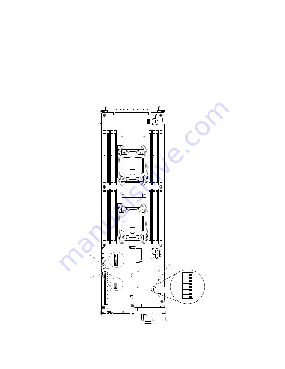
Recovery BIOS Function by SW1

This section details the recovery BIOS Function by SW1.

Step 1.

Pull out the node and place SW1 DIP1 to “ON” location.

00000000

1

2

3

1

2

3

4

Clear CMOS jumper

8
7
6
5
4
3
2
1

ON

SATADOM power jumper
(JP136)

Switch block 1 (SW1)

Figure 16. Location of the switches, jumpers, and buttons on the system board

64

Lenovo ThinkServer sd350 Server Type 5493, Lenovo ThinkServer n400 Enclosure Type 5495Installation and Service Guide

Содержание ThinkServer n400

Страница 1: ...Lenovo ThinkServer sd350 Server Type 5493 Lenovo ThinkServer n400 Enclosure Type 5495 Installation and Service Guide Machine Type Type 5493 and 5495 ...

Страница 2: ...y Information document and the Safety Information and Environmental Notices and User Guide documents on the Lenovo Documentation CD First Edition Sept 26 2016 Copyright Lenovo LIMITED AND RESTRICTED RIGHTS NOTICE If data or software is delivered pursuant to a General Services Administration GSA contract use reproduction or disclosure is subject to restrictions set forth in Contract No GS 35F 05925...

Страница 3: ... problems 43 Service bulletins 43 Checkout procedure 43 About checkout procedure 43 Performing the checkout procedure 44 Diagnostic tools 44 System error LEDs 45 System event logs 47 POST 49 Error messages 49 Troubleshooting by symptom 49 General problems 49 Hard disk drive problems 50 Intermittent problems 52 Keyboard mouse or USB device problems 53 Memory problems 53 Monitor problems 54 Network ...

Страница 4: ... interface board 138 Installing the power interface board 139 Removing the power interface board bracket 140 Installing the power interface board bracket 141 Removing the system management board and backplane assembly 142 Installing the system management board and backplane assembly 143 Internal cable routing and connectors 144 Removing the node SATA cable 148 Installing the node SATA cable 149 Ap...

Страница 5: ...Taiwan BSMI RoHS declaration 182 Index 183 Copyright Lenovo iii ...

Страница 6: ...iv Lenovo ThinkServer sd350 Server Type 5493 Lenovo ThinkServer n400 Enclosure Type 5495Installation and Service Guide ...

Страница 7: ...hriften Ennen kuin asennat tämän tuotteen lue turvaohjeet kohdasta Safety Information Avant d installer ce produit lisez les consignes de sécurité Vor der Installation dieses Produkts die Sicherheitshinweise lesen Prima di installare questo prodotto leggere le Informazioni sulla Sicurezza Les sikkerhetsinformasjonen Safety Information før du installerer dette produktet Antes de instalar este produ...

Страница 8: ...anger statement with translated versions of the caution or danger statement in the Safety Information document For example if a caution statement is labeled Statement 1 translations for that caution statement are in the Safety Information document under Statement 1 Be sure to read all caution and danger statements in this documentation before you perform the procedures Read any additional safety i...

Страница 9: ... and disconnect cables as described in the following table when installing moving or opening covers on this product or attached devices To Connect To Disconnect 1 Turn everything OFF 2 First attach all cables to devices 3 Attach signal cables to connectors 4 Attach power cords to outlet 5 Turn device ON 1 Turn everything OFF 2 First remove power cords from outlet 3 Remove signal cables from connec...

Страница 10: ...nce of procedures other than those specified herein might result in hazardous radiation exposure DANGER Some laser products contain an embedded Class 3A or Class 3B laser diode Note the following Laser radiation when open Do not stare into the beam do not view directly with optical instruments and avoid direct exposure to the beam Statement 4 CAUTION Use safe practices when lifting 18 kg 39 7 lb 3...

Страница 11: ... install a strain relief bracket option over the end of the power cord that is connected to the device you must connect the other end of the power cord to an easily accessible power source Statement 8 CAUTION Never remove the cover on a power supply or any part that has the following label attached Hazardous voltage current and energy levels are present inside any component that has this label att...

Страница 12: ...nts Refer to the information that is provided with your device for electrical specifications Statement 14 CAUTION Hazardous voltage current and energy levels might be present Only a qualified service technician is authorized to remove the covers where the following label is attached Statement 15 CAUTION Make sure that the rack is secured properly to avoid tipping when the server unit is extended x...

Страница 13: ...Statement 26 CAUTION Do not place any object on top of rack mounted devices Statement 27 CAUTION Hazardous moving parts are nearby Copyright Lenovo xi ...

Страница 14: ...g table when you install move or open covers on this product or attached devices To Connect To Disconnect 1 Turn OFF all power sources and equipment that is to be attached to this product 2 Attach signal cables to the product 3 Attach power cords to the product For ac systems use appliance inlets For dc systems ensure correct polarity of 48 V dc connections RTN is and 48 V dc is Earth ground shoul...

Страница 15: ...lable approved and rated disconnect device in the field wiring See the specifications in the product documentation for the required circuit breaker rating for branch circuit overcurrent protection Use copper wire conductors only See the specifications in the product documentation for the required wire size See the specifications in the product documentation for the required torque values for the w...

Страница 16: ...xiv Lenovo ThinkServer sd350 Server Type 5493 Lenovo ThinkServer n400 Enclosure Type 5495Installation and Service Guide ...

Страница 17: ...create a personalized support page by identifying Lenovo products that are of interest to you From this personalized page you can subscribe to weekly email notifications about new technical documents search for information and downloads and access various administrative services The Lenovo ThinkServer sd350 Server Type 5493 Lenovo ThinkServer n400 Enclosure Type 5495 supports up to twenty four 2 5...

Страница 18: ...0000000000000000000000000 0000000000000000000000000000 0000000000000000000000000000 0000000000000000000000000000 0000000000000000000000000000 0000000000000000000000000000 0000000000000000000000000000 0000000000000000000000000000 0000000000000000000000000000 0000000000000000000000000000 0000000000000000000000000000 0000000000000000000000000000 0000000000000000000000000000 00000000000000000000000000...

Страница 19: ...nux operating systems The Documentation Browser Use the Documentation Browser to browse the contents of the CD read brief descriptions of the documents and view documents using Adobe Acrobat Reader or xpdf The Documentation Browser automatically detects the regional settings in use in your server and displays the documents in the language for that region if available If a document is not available...

Страница 20: ...document is in PDF format on the Lenovo Documentation CD It contains translated environmental notices Lenovo License Agreement for Machine Code This document is in PDF format on the Lenovo Documentation CD It provides translated versions of the Lenovo License Agreement for Machine Code for your product Important Notices This document is in printed format and comes with the server It contains infor...

Страница 21: ...de nos 601a commandref index html Network OS Message Reference http www brocade com content html en message reference guides nos 601a messageref wwhelp wwhimpl js html wwhelp htm FC5022 User Guide Fabric OS Administrator s Guide http www brocade com content html en administration guide fos 740 adminguide Fabric OS Command Reference http www brocade com content html en command reference guide fos 7...

Страница 22: ...ct QPI links speed up to 9 6 GT per second Notes 1 Use the Setup utility to determine the type and speed of the microprocessors in the server 2 For a list of supported microprocessors see http www lenovo com us en serverproven Memory Sixteen DIMM connectors per node eight per microprocessor Support RDIMM 8 GB 16 GB 32 GB memory capacities Types PC4 19200 dual rank 2400 MHz ECC DDR4 registered DIMM...

Страница 23: ...ession Video memory is not expandable Note Maximum video resolution is 1920 x 1200 at 60 Hz Size 2U chassis Height 87 mm 3 43 inches Depth 835 mm 32 9 inches Width 442 mm 17 40 inches Weight Minimum configuration with one node 22 4 kg 49 lbs Maximum configuration with four nodes 36 9 kg 81 lbs Node Height 41 mm 1 62 inches Depth 572 mm 22 51 inches Width 171 mm 6 74 inches Weight Minimum weight 2 ...

Страница 24: ...ature 40 C to 60 C 40 F 140 F Altitude 10700 m 35105 ft Relative humidity 5 100 Maximum dew point 29 C 84 2 F Fan fails mode When any fan fails and ambient temperature is above 27 C system performance may be degraded and have an event log indicated Heat output based on 1600 Watts Approximate heat output Minimum configuration 604 1 BTU per hour 177 watts Maximum configuration 6051 3 BTU per hour 17...

Страница 25: ...asic System Management The TMM combines service processor functions video controller and remote presence and blue screen capture features in a single chip The TMM provides advanced service processor control monitoring and alerting function If an environmental condition exceeds a threshold or if a system component fails the TMM lights LEDs to help you diagnose the problem records the error in the T...

Страница 26: ...tus and sensor status The program also enables users to perform management tasks such as restarting or turning off your ThinkServer server launching a remote console and accessing the Thinkserver Management Module TMM interface For detailed information about using the program refer to the help system of the program Lenovo Partner Pack for VMware vCenter The Lenovo Partner Pack for VMware vCenter p...

Страница 27: ...i based and Hyper V environments see http pic dhe ibm com infocenter flexsys information index jsp topic 2Fcom lenovo lxca doc 2 Fsetup html Free 90 day trial Lenovo XClarity Administrator offers a free 90 day trial license that enables you to use all available features including operating system deployment firmware maintenance and configuration management for a limited time After 90 days you can ...

Страница 28: ...stem BIOS compatibility support UEFI replaces the BIOS and defines a standard interface between the operating system platform firmware and external devices The server is capable of booting UEFI compliant operating systems BIOS based operating systems and BIOS based adapters as well as UEFI compliant adapters Lenovo XClarity Administrator Lenovo XClarity Administrator is a centralized resource mana...

Страница 29: ...ystem endpoints More information about Lenovo XClarity Administrator is available at http shop lenovo com us en systems software systems management xclarity SMASH CLP SMASH CLP System Management Architecture for Server Hardware Command Line Protocol is a command line protocol that simplifies cross platform management and provides a simple way to access as well as manage manageable entities via CIM...

Страница 30: ...e admin target cd admin1 Command Status COMMAND COMPLETED ufip admin1 show Verb It is used to show the information about a particular target collection or association It displays the sub targets contained within the given target it s properties supported operation verbs and list of other targets to which it is associated Eg The below command show admin1 system1 sp1 sshsvc1 will display all the inf...

Страница 31: ...the SMASH CLP application exit Command OK COMMAND COMPLETED help Verb The is used to get context sensitive help The functionality is the same as the help option with the addition of help for targets Eg The below command help will display the usage of the SMASH CLP application help Command Status COMMAND COMPLETED SMASH CLP is a command line interface for the remote user to the server The commands ...

Страница 32: ...m1 sp1 Properties Name IPMI Controller 32 CreationClassName DCIM_ComputerSystem ElementName ibmc EnabledState 2 RequestedState 11 HealthState 5 IdentifyingDescriptions Manufacturer ID Product ID OtherIdentifyingInfo 16220 187170 OperationalStatus 2 Dedicated 28 start Verb This is used to cause a target with power process control to change states to a higher run level Eg The below command start adm...

Страница 33: ... the profiles and specific MAP implementation Standard CLP Verbs Options Output Option This option is used to view the command results in different format It has many arguments like order count etc one of which is format which outputs the result in text or clpxml or keyword By default the output is displayed in text format Eg The below command cd o format clpxml admin1 system1 instructs the comman...

Страница 34: ...dmin1 Command Status COMMAND COMPLETED ufip admin1 Properties Name MAP CreationClassName CIM_AdminDomain ElementName SM CLP Admin Domain Eg 2 e below command show d properties verbs admin1 instructs the command processor to display only the properties verbs of admin target show d properties verbs admin1 Command Status COMMAND COMPLETED ufip admin1 Properties Name MAP CreationClassName DCIM_AdminDo...

Страница 35: ...dundancy Diagnostic support for RAID and Ethernet adapters Error codes and messages Error correcting code ECC and system memory Cooling fans with speed sensing capability Hot swap hard disk drives Memory error correcting code and parity test Microprocessor built in self test BIST internal error signal monitoring internal thermal trip signal monitoring configuration checking and microprocessor and ...

Страница 36: ...drive 2 5 inch hard disk drive filler panel 2 5 inch HDD hot swap backplane Fan cage Fan Fan board Power interface board bracket Power interface board Fan cover PCI riser card assembly LAN Mezz card HBA Mezz card Heat sink CPU2 Heat sink CPU1 Air baffle Microprocessor DIMM Node system Power supply System management board cover System management board power backplane 2 5 inch hard disk drive x4 fil...

Страница 37: ...t view The following illustration shows the controls LEDs and connectors on the front of the server Note The illustrations in this document might differ slightly from your hardware The following illustration shows the control panels and the 2 5 inch hot swap hard disk drives 0 0 0 0 0 0 0000000000000000000000000000000000000 0 0 0 0 00 00 00 00 00 00 00 00 00 00 00 00 00 00 00 00 00 00 00 00 00 00 ...

Страница 38: ...tors Low profile PCIe slot Optional Figure 7 Connectors on the rear of the server The following illustration shows the rear view of the entire system 00 00 00 00 00 00 00 0 00000 00000 0 00000 00000 00 00000 00000 00 00000 00000 Node 4 Node 2 Node 3 Node 1 Power supply 1 Power supply 2 Power cord connectors Figure 8 The rear view of the entire system Power button LED When this LED is lit green it ...

Страница 39: ...M through NC SI interface Video connector Connect a monitor to this connector USB connectors Connect a USB device such as a USB mouse keyboard or other device to any of these connectors Power cord connector Connect the power cord to this connector System board internal connectors The following illustration shows the internal connectors on the system board Chapter 1 The Lenovo ThinkServer sd350 Ser...

Страница 40: ...onnector HBA mezzanine connector OCP mezzanine connector PCIe riser connector JP18 SATA connector JPT1 SATA SAS connector For SATADOM install Figure 9 Internal connectors on the system board System board external connectors The following illustration shows the external connectors on the system board 24 Lenovo ThinkServer sd350 Server Type 5493 Lenovo ThinkServer n400 Enclosure Type 5495Installatio...

Страница 41: ...he location and description of the switches jumpers and buttons Important 1 Before you change any switch settings or move any jumpers turn off the server then disconnect external cables Review the information in Safety on page v Installation guidelines on page 75 and Turning off the server on page 29 Chapter 1 The Lenovo ThinkServer sd350 Server Type 5493 Lenovo ThinkServer n400 Enclosure Type 549...

Страница 42: ...discard it to access the switches 00000000 1 2 3 1 2 3 4 Clear CMOS jumper 8 7 6 5 4 3 2 1 ON SATADOM power jumper JP136 Switch block 1 SW1 Figure 11 Location of the switches jumpers and buttons on the system board The following table describes the jumpers on the system board 26 Lenovo ThinkServer sd350 Server Type 5493 Lenovo ThinkServer n400 Enclosure Type 5495Installation and Service Guide ...

Страница 43: ...ADOM power jumper The following table describes the functions of the SW1 switch block on the system board Table 3 System board SW1 switch block definition Switch number Default position Description 1 Off BIOS recovery 2 Off ME recovery 3 Off Default off 4 Off Password clear System board LEDs The following illustration shows the light emitting diodes LEDs on the system board Chapter 1 The Lenovo Th...

Страница 44: ...e operating system does not run and all core logic except for the TMM is shutdown However the server can respond to requests from TMM such as a remote request to turn on the server The power on LED will not be lit when the server is connected to ac power but is not turned on 28 Lenovo ThinkServer sd350 Server Type 5493 Lenovo ThinkServer n400 Enclosure Type 5495Installation and Service Guide ...

Страница 45: ...em the configuration of the server and the configured PCI options Turning off the server Use this information to turn off the server When you turn off the server and leave it connected to ac power the server can respond to requests from ThinkServer Management Module TMM such as a remote request to turn on the server While the server remains connected to ac power one or more fans might continue to ...

Страница 46: ...ff the server The server can be turned off by Wake on LAN feature with the following limitation Note When you install any PCI adapter the power cords must be disconnected from the power source before you remove the PCI Express assembly Otherwise the Wake on LAN feature might not work The TMM can turn off the server as an automatic response to a critical system failure 30 Lenovo ThinkServer sd350 S...

Страница 47: ...test Firmware Updater ISO image And burn the ISO image into CD DVD or USB disk Notes Use rufus to burn the ISO image into USB disk a Decompress rufus_v1 3 4 exe from the directory usbutility of ISO image and then execute it b Insert an empty USB key into a USB slot of your computer Please note that the USB will be formatted during this procedure and all the contents will be lost c In the drop down...

Страница 48: ...ity and blue screen capture The remote presence and blue screen capture features are integrated functions of the TMM The remote presence feature provides the following functions Remotely viewing video with graphics resolutions up to 1024 x 768 regardless of the system state Remotely accessing the server using the keyboard and mouse from a remote client Mapping the CD or DVD drive diskette drive an...

Страница 49: ...ot If it is a Windows OS it can also support the following settings Organization Product ID Workgroup Domain Configure the network Adapters Time Zone It detects the installed hardware on the system and installs the device drivers based on the hardware detected EasyStartup features This information provides an overview of the EasyStartup features The EasyStartup program has the following features P...

Страница 50: ...tings Resolve configuration conflicts Starting the Setup utility Use this information to start up the Setup utility To start the Setup utility complete the following steps Step 1 Turn on the server Note Approximately 5 to 10 seconds after the server is connected to power the power control button becomes active Step 2 When the prompt F1 Setup is displayed press F1 If you have set an administrator p...

Страница 51: ... settings Legacy Console Redirection Setting Console Redirection Settings PCI Subsystem Settings Select this to view or change the PCI Devices common settings Network Stack Configuration Select this to view or change Network Stace IPV4 and IPV6 PXE Support settings CSM Configuration Select this to view or change CSM Support and Netwrok Storage Video Other PCI devices legacy support Infor Report Co...

Страница 52: ...abled to active or not active the sparing mode Note You can not choose to enable sparing and mirroring modes at the same time In case if the mirror mode is enabled sparing mode will not be selected IIO Configuration Select this to view or change Intel Chipset IIO Configuration IIO0 Configuration IIO1 Configuration Intel VT for Directed I O VT d PCH Configuration Select this to view or change PCH C...

Страница 53: ...sword to complete the system startup but you must type the administrator password to access the Setup utility menu If you set a power on password for a user and an administrator password for a system administrator you must type the power on password to complete the system startup A system administrator who types the administrator password has access to the full Setup utility menu the system admini...

Страница 54: ...am is a built in menu driven configuration utility program that you can use to temporarily redefine the first startup device without changing settings in the Setup utility To use the Boot Manager program complete the following steps Step 1 Turn off the server Step 2 Restart the server Step 3 When the prompt F1 Setup screen is displayed move cursor Right Key to select Boot page press Enter Step 4 U...

Страница 55: ... and soft reset schedule power control Query power supply input power ROM based TMM firmware flash updates Serial over LAN SOL Serial port redirection over telnet or ssh SMI handling System event log SEL user readable event log The TMM also provides the following remote server management capabilities through the ipmitool a management utility program Command line interface IPMI Shell The command li...

Страница 56: ... password If you are using the TMM for the first time you can obtain the user name and password from your system administrator All login attempts are documented in the system event log Note The TMM is set initially with user name of USERID and password of PASSW0RD with a zero not the letter O You d have read write access and must change the default password when you log in for the first time Step ...

Страница 57: ...was in before the problem occurred If any hardware software or firmware was changed before the problem occurred if possible reverse those changes This might include any of the following items Hardware components Device drivers and firmware System software UEFI firmware System input power or network connections Step 2 View the System error LEDs and event logs The server is designed for ease of diag...

Страница 58: ...igured a system function can fail to work when you enable it if you make an incorrect change to the server configuration a system function that has been enabled can stop working a Make sure that all installed hardware and software are supported See http www lenovo com us en serverproven to verify that the server supports the installed operating system optional devices and software levels If any ha...

Страница 59: ...for assistance To open an online service request go to http www lenovo com support Be prepared to provide information about any error codes and collected data and the problem determination procedures that you have used Service bulletins Lenovo continually updates the support website with the latest tips and techniques that you can use to solve problem that you might have with the Lenovo ThinkServe...

Страница 60: ...more information Successful completion of startup which is indicated by a readable display of the operating system desktop Step 3 Is there a readable image on the monitor screen No Find the failure symptom in Troubleshooting by symptom on page 49 if necessary see Solving undetermined problems on page 60 Yes Run LTD If LTD reports an error follow the instructions in Appendix B Diagnostic error mess...

Страница 61: ...try standard interfaces Intelligent Platform Management Protocol IPMI version 2 0 Simple Network Management Protocol SNMP version 3 Common Information Model CIM Web browser For more information about the TMM see Using the TMM on page 38 TMM error messages on page 152 Troubleshooting by symptom These tables list problem symptoms and actions to correct the problems See Troubleshooting by symptom on ...

Страница 62: ...problem when the operating system is shut down Note When you disconnect the power source from the server you lose the ability to view the LEDs because the LEDs are not lit when the power source is removed Before you disconnect the power source make a note of which LEDs are lit including the LEDs that are lit on the operation information panel and LEDs inside the server on the system board 46 Lenov...

Страница 63: ... have to save and then clear the system event log to make the most recent events available for analysis Messages are listed on the left side of the screen and details about the selected message are displayed on the right side of the screen To move from one entry to the next use the Up Arrow and Down Arrow keys Some TMM sensors cause assertion events to be logged when their setpoints are reached Wh...

Страница 64: ...ds Run diagnostic tool Lenovo ToolsCenter Suite CLI to view the diagnostic event log requires IPMI driver or create an output file that you can send to Lenovo service and support using ftp or local copy Use IPMItool to view the system event log requires IPMI driver The server is not hung and is not connected to a network using an operating system controlled network ports Run diagnostic tool Lenovo...

Страница 65: ...pendix B Diagnostic error messages on page 169 for more information about testing the server For additional information to help you solve problems see Start here on page 41 If you have just added new software or a new optional device and the server is not working complete the following steps before you use the troubleshooting tables Step 1 Check the system error LED on the operator information pan...

Страница 66: ...If an action step is preceded by Trained technician only that step must be performed only by a Trained technician Go to the Lenovo support website at http www lenovo com support to check for technical information hints tips and new device drivers or to submit a request for information Table 6 Hard disk drive symptoms and actions Symptom Action Not all drives are recognized by the hard disk drive d...

Страница 67: ...e whether the drive is detected If the green activity LED is flashing and the yellow status LED is flashing slowly the drive is recognized by the controller and is rebuilding If neither LED is lit or flashing check the hard disk drive backplane go to step 4 If the green activity LED is flashing and the yellow status LED is lit replace the drive If the activity of the LEDs remains the same go to st...

Страница 68: ...llow hard disk drive status LED does not accurately represent the actual state of the associated drive Hot swap hard disk drives 1 If the yellow hard disk drive LED and the RAID adapter software do not indicate the same status for the drive complete the following steps a Turn off the server b Reseat the SAS SATA adapter c Reseat the backplane configuration cable signal cable and backplane power ca...

Страница 69: ...orrectly The server and the monitor are turned on The mouse option is enabled in the Setup utility 2 If you are using a USB mouse or USB device and it is connected to a USB hub disconnect the mouse or USB device from the hub and connect it directly to the server 3 Replace the mouse or USB device Memory problems Follow the suggested actions in the order in which they are listed in the Action column...

Страница 70: ...board Multiple rows of DIMMs in a branch are identified as failing Note Each time you install or remove a DIMM you must disconnect the server from the power source then wait 10 seconds before restarting the server 1 Reseat the DIMMs then restart the server 2 Replace the failing DIMM 3 Trained technician only Replace the system board Monitor problems Some Lenovo monitors have their own self tests I...

Страница 71: ...deo adapter if one is installed c Trained technician only System board 7 See Solving undetermined problems on page 60 The monitor works when you turn on the server but the screen goes blank when you start some application programs 1 Make sure that The application program is not setting a display mode that is higher than the capability of the monitor You installed the necessary device drivers for t...

Страница 72: ...ure the license key is valid 2 Generate a new license key and log in again Optional device problems Follow the suggested actions in the order in which they are listed in the Action column until the problem is solved If an action step is preceded by Trained technician only that step must be performed only by a Trained technician Go to the Lenovo support website at http www lenovo com support to che...

Страница 73: ...re that the power control button is working correctly a Disconnect the server power cords b Reconnect the power cords c Trained technician only Reseat the operator information panel cable and then repeat steps 1a and 1b Trained technician only If the server starts reseat the operator information panel If the problem remains replace the operator information panel If the server does not start bypass...

Страница 74: ...lems on page 60 Software problems Follow the suggested actions in the order in which they are listed in the Action column until the problem is solved If an action step is preceded by Trained technician only that step must be performed only by a Trained technician Go to the Lenovo support website at http www lenovo com support to check for technical information hints tips and new device drivers or ...

Страница 75: ...ondition To diagnose a power problem use the following general procedure Step 1 Turn off the server and disconnect all power cords Step 2 Check for loose cables in the power subsystem Also check for short circuits for example if a loose screw is causing a short circuit on a circuit board Step 3 Turn on the server and check the LEDs Step 4 Turn off the server and disconnect all power cords Step 5 R...

Страница 76: ...ata is active on the Ethernet network If the LAN activity LED is off make sure that the hub and network are operating and that the correct device drivers are installed Step 6 Check for operating system specific causes of the problem Step 7 Make sure that the device drivers on the client and server are using the same protocol If the Ethernet controller still cannot connect to the network but the ha...

Страница 77: ...r if the problem recurs when you replace the adapter with a different one suspect the riser card If you suspect a networking problem and the server passes all the system tests suspect a network cabling problem that is external to the server Problem determination tips Because of the variety of hardware and software combinations that can encounter use the following information to assist you in probl...

Страница 78: ...000 0000000000000000000000000000 0000000000000000000000000000 0000000000000000000000000000 0000000000000000000000000000 0000000000000000000000000000 0000000000000000000000000000 0000000000000000000000000000 0000000000000000000000000000 0000000000000000000000000000 0000000000000000000000000000 0000000000000000000000000000 0000000000000000000000000000 0000000000000000000000000000 0000000000000000000...

Страница 79: ... cluster solution before you update the code If the server firmware has become corrupted such as from a power failure during an update you can recover the server firmware in the following way Recovery BIOS Function Recovery BIOS Function by SW1 Notes You can obtain a server update package from one of the following sources Download the server firmware update from the World Wide Web Contact your Len...

Страница 80: ...ate Recovery BIOS Function by SW1 This section details the recovery BIOS Function by SW1 Step 1 Pull out the node and place SW1 DIP1 to ON location 00000000 1 2 3 1 2 3 4 Clear CMOS jumper 8 7 6 5 4 3 2 1 ON SATADOM power jumper JP136 Switch block 1 SW1 Figure 16 Location of the switches jumpers and buttons on the system board 64 Lenovo ThinkServer sd350 Server Type 5493 Lenovo ThinkServer n400 En...

Страница 81: ... follow same procedure to remove USB key place SW1 DIP1 to OFF location Out of band recovery method If the server firmware has become corrupted such as from a power failure during an update you can recover the server firmware by using Out Of_Band Recovery method For additional information see the TMM User Guide Thinkserver SD350 System Manager User Guide pdf at http www lenovo com support and Chap...

Страница 82: ...66 Lenovo ThinkServer sd350 Server Type 5493 Lenovo ThinkServer n400 Enclosure Type 5495Installation and Service Guide ...

Страница 83: ...ll be charged for the service See Structural parts on page 72 for the list of structural parts Tier 1 customer replaceable unit CRU Replacement of Tier 1 CRUs is your responsibility If Lenovo installs a Tier 1 CRU at your request you will be charged for the installation Tier 2 customer replaceable unit You may install a Tier 2 CRU yourself or request Lenovo to install it at no additional charge un...

Страница 84: ...0000000000 00000000000000 00000000000000 00000000000000 00000000000000 00000000000000 00000000000000 00000000000000 00 00 000 000 000 000 000 000 000 00 00 00 00 00 8 10 3 1 22 21 20 19 18 17 16 15 14 13 12 11 2 4 5 6 7 9 Figure 17 Server components 68 Lenovo ThinkServer sd350 Server Type 5493 Lenovo ThinkServer n400 Enclosure Type 5495Installation and Service Guide ...

Страница 85: ... inch S3510 G3 hot swap 480 GB enterprise entry SATA 00WG631 8 Hard disk drive 2 5 inch G3 hot swap 300 GB 15 K 12 Gbps SAS 00WG661 8 Hard disk drive 2 5 inch G3 hot swap 600 GB 15 K 12 Gbps SAS 00WG666 8 Hard disk drive 2 5 inch G3 hot swap 300 GB 10 K 12 Gbps SAS 00WG686 8 Hard disk drive 2 5 inch G3 hot swap 600 GB 10 K 12 Gbps SAS 00WG691 8 Hard disk drive 2 5 inch G3 hot swap 900 GB 10 K 12 G...

Страница 86: ...MB 1866 MHz 85 W 8 core 00MW782 16 Microprocessor Intel Xeon E5 2603 v4 1 7 GHz 15 MB 1866 MHz 85 W 6 core 00MW783 16 Microprocessor Intel Xeon E5 2690 v4 2 6 GHz 35 MB 2400 MHz 135 W 14 core 00YD969 16 Microprocessor Intel Xeon E5 2680 v4 2 4 GHz 35 MB 2400 MHz 120 W 14 core 00YD970 16 Microprocessor Intel Xeon E5 2660 v4 2 0 GHz 35 MB 2400 MHz 105 W 14 core 00YD971 16 Microprocessor Intel Xeon E...

Страница 87: ... Cable rack power 1 0m C13 to C14 jumper cord 39M5374 Cable rack power 2 8m 10A 100 250V C13 to IEC 320 C14 39M5377 Cable rack power 2 8m 10A 100 250V C13 to IEC 320 C20 39M5392 Cable rack power 1 345m 2X C13 to C14 jumper cord 39M5401 Cable rack power 2 054m 2X C13 to C14 jumper cord 39M5450 Cable rack power 2 5m 16A 100 250V 2 long C13s to short C20 69Y1627 Node air baffle 00YD553 Emulex VFA5 2x...

Страница 88: ...he Products menu select Upgrades accessories parts 3 Click Obtain maintenance parts then follow the instructions to order the part from the retail store Note Changes are made periodically to the Lenovo website The actual procedure might vary slightly from what is described in this document If you need help with your order call the toll free number that is listed on the retail parts page or contact...

Страница 89: ...ania Mauritius Mayotte Moldova Republic of Monaco Mongolia Morocco Mozambique Netherlands New Caledonia Niger Norway Poland Portugal Reunion Romania Russian Federation Rwanda Sao Tome and Principe Saudi Arabia Senegal Serbia Slovakia Slovenia Republic of Somalia Spain Suriname Sweden Syrian Arab Republic Tajikistan Tahiti Togo Tunisia Turkey Turkmenistan Ukraine Upper Volta Uzbekistan Vanuatu Viet...

Страница 90: ...Federal States of Netherlands Antilles Nicaragua Panama Peru Philippines Saudi Arabia Thailand Taiwan United States of America Venezuela 39M5463 Taiwan 39M5087 Thailand 39M5219 Korea Democratic People s Republic of Korea Republic of 39M5199 Japan 39M5068 Argentina Paraguay Uruguay 39M5226 India 39M5240 39M5241 Brazil 39M5375 39M5377 39M5378 39M5509 39M5512 Canada United States of America 74 Lenovo...

Страница 91: ...able as both an optional device and a replaceable component The installation procedure is the same for the optional device and the replaceable component Installation guidelines Before you remove or replace a replaceable component or install an optional device read the following information Before you begin read Safety on page v and Handling static sensitive devices on page 76 This information will...

Страница 92: ...the server for at least 2 seconds This drains static electricity from the package and from your body Remove the device from its package and install it directly into the server without setting down the device If it is necessary to set down the device put it back into its static protective package Do not place the device on the server cover or on a metal surface Take additional care when handling de...

Страница 93: ... 000 000000 000000 000000 000000 Latch Handle 1 2 Attention To maintain proper system cooling do not operate the Lenovo ThinkServer n400 Enclosure Type 5495 chassis without a compute node or node bay filler installed in each node bay When you remove the compute node note the node bay number Reinstalling a compute node into a different node bay from the one it was removed from can have unintended c...

Страница 94: ...nto a different node bay can have unintended consequences If you reinstall the compute node into a different node bay you might have to reconfigure the compute node 2 To maintain proper system cooling do not operate the Lenovo ThinkServer n400 Enclosure Type 5495 chassis without a compute node or node bay filler in each node bay Step 2 Install the air baffle properly in the position before sliding...

Страница 95: ...ng and replacing structural parts in the server Replacement of structural parts is your responsibility If Lenovo installs a structural part at your request you will be charged for the installation The illustrations in this document might differ slightly from your hardware Removing the shipping brackets kit Use this information to remove the shipping brackets kit from the server To remove the shipp...

Страница 96: ...alling the shipping brackets kit Use this information to install the shipping brackets kit into the server Note If you plan to transport the rack to another location you must install the support brackets that come with the chassis You can replace the shipping brackets kit by either via Replaceable server components on page 67 or you can order it as an option To install the shipping brackets kit co...

Страница 97: ...hassis Make sure that the thinner face is displayed outwards C clips Figure 21 Installing the four C clips Step 3 Align the shipping brackets with the flanges and rails and install the four two on each side M6 screws to the brackets on the rear of the chassis M6 screws Shipping bracket Figure 22 Installing the shipping brackets Step 4 Install the two one on each side 10 32 screws to the brackets o...

Страница 98: ...l attached peripheral devices Disconnect all power cords then disconnect all external cables as necessary to replace the device Statement 12 CAUTION The following label indicates a hot surface nearby Statement 21 CAUTION Hazardous energy is present when the compute node is connected to the power source Always replace the compute node cover before installing the compute node To remove the fan cage ...

Страница 99: ...cage cover Before you install the fan cage cover read Safety on page v and Installation guidelines on page 75 If you are replacing the cover make sure that you have the system service label kit on hand for use during the replacement procedure Statement 21 CAUTION Hazardous energy is present when the compute node is connected to the power source Always replace the compute node cover before installi...

Страница 100: ...e 3 M3 screws Step 5 To install a system service label which needs to be ordered separately align the label on the cover remove the backing and press the label on the cover Removing the system management board cover Use this information to remove the cover from a system management board Before you remove the system management board cover complete the following steps 1 Read Safety on page v and Ins...

Страница 101: ...00000000000000000 00000000000000000 00000000000000000 00000000000000000 00000000000000000 00000000000000000 00000000000000000 00000000000000000 00000000000000000 00000000000000000 00000000000000000 00000000000000000 screws Figure 24 System management board cover removal Step 4 Lay the cover flat or store it for future use If you are instructed to return the cover follow all packaging instructions ...

Страница 102: ...anagement board cover so that the posts on the inside of the cover slide into the slots on the system 000 000 000 0 0 00 00 00 00 00 00000000000000000 00000000000000000 00000000000000000 00000000000000000 00000000000000000 00000000000000000 00000000000000000 00000000000000000 00000000000000000 00000000000000000 00000000000000000 00000000000000000 00000000000000000 00000000000000000 000000000000000...

Страница 103: ...0 0000 0000 0000 0000 0000 0000 0000 0000 Air baffle Figure 26 Air baffle removal Attention For proper cooling and airflow replace the air baffle before you turn on the server Operating the server with the air baffle removed might damage server components Installing the air baffle Use this information to replace the air baffle Read the safety information in Safety on page v and Installation guidel...

Страница 104: ...er slightly from your hardware Removing a system fan Use this information to remove a system fan in the server Read the safety information in Safety on page v and Installation guidelines on page 75 Attention Static electricity that is released to internal server components when the server is powered on might cause the server to halt which might result in the loss of data To avoid this potential pr...

Страница 105: ...h Figure 28 System fans If you are instructed to return the server component or optional device follow all packaging instructions and use any packaging materials for shipping that are supplied to you Replacing a system fan Use this information to replace a system fan in the server Read the safety information in Safety on page v and Installation guidelines on page 75 Attention Static electricity th...

Страница 106: ...ks into place 2 Reconnect the power cords and any cables that you removed 3 Turn on the peripheral devices and the server Removing a hot swap hard disk drive Use this information to remove a hot swap hard disk drive Attention To avoid damage to the hard disk drive connectors make sure that the server cover is in place and fully closed whenever you install or remove a hard disk drive To make sure t...

Страница 107: ...e following notes describe the type of hard disk drives that the server supports and other information that you must consider when you install a hard disk drive For a list of supported hard disk drives see http www lenovo com us en serverproven Locate the documentation that comes with the hard disk drive and follow those instructions in addition to the instructions in this chapter Make sure that y...

Страница 108: ...p 2 Touch the static protective package that contains the drive to any unpainted metal surface on the server then remove the drive from the package and place it on a static protective surface Step 3 Install the hard disk drive in the drive bay a Make sure that the tray handle is in the open unlocked position b Align the drive with the guide rails in the bay 0 0 0 0 0 0 0 0000000000000000000000 000...

Страница 109: ...ow Removing a DIMM Use this information to remove a memory module Read the safety information in Safety on page v and Installation guidelines on page 75 If you are replacing a server component or installing an optional device in the server you need to take out the node out from the rack enclosure turn off the server and peripheral devices and disconnect all external cables To remove a dual inline ...

Страница 110: ...the DIMMs that you install in DIMM connectors 1 and 3 must match each other However they do not have to be the same size and speed as the DIMMs that are installed in DIMM connectors 2 and 4 You can use compatible DIMMs from various manufacturers in the same pair The specifications of a DDR4 DIMM are on a label on the DIMM in the following format gggGBpheRxff PC4 wwwwaa mccd bb where gggGB is the t...

Страница 111: ...le used for this design d is the revision number of the reference design used bb is the JEDEC SPD Revision Encoding and Additions level used on this DIMM The following illustration shows the location of the DIMM connectors on the system board DIMM G1 DIMM G2 DIMM H1 DIMM H2 DIMM E1 DIMM E2 DIMM F1 DIMM F2 DIMM C1 DIMM C2 DIMM D1 DIMM D2 DIMM A1 DIMM A2 DIMM B1 DIMM B2 Microprocessor 2 Microprocess...

Страница 112: ... inside the server with the power on The following illustration shows the location of the DIMM connectors on the system board DIMM G1 DIMM G2 DIMM H1 DIMM H2 DIMM E1 DIMM E2 DIMM F1 DIMM F2 DIMM C1 DIMM C2 DIMM D1 DIMM D2 DIMM A1 DIMM A2 DIMM B1 DIMM B2 Microprocessor 2 Microprocessor 1 Figure 34 The location of the DIMM connectors on the system board To install a DIMM complete the following steps...

Страница 113: ...lled A1 B1 C1 D1 A2 B2 C2 D2 Microprocessor 1 and 2 installed A1 B1 E1 F1 C1 D1 G1 H1 A2 B2 E2 F2 C2 D2 G2 H2 Step 4 Open the retaining clip on each end of the DIMM connector Attention To avoid breaking the retaining clips or damaging the DIMM connectors open and close the clips gently DIMM Retaining clip Alignment tab Alignment slot Figure 35 DIMM installation Step 5 Touch the static protective p...

Страница 114: ...er you need slide the server into the rack reconnect the power cords and all external cables and turn on the server and peripheral devices Removing a hot swap power supply Use this information to remove a hot swap power supply When you remove or install a hot swap power supply observe the following precautions Statement 5 CAUTION The power control button on the device and the power switch on the p...

Страница 115: ...cord from the connector on the back of the power supply Step 3 Press and hold the orange release tab to the left 00 00 00 00 00 00 000 000 000 000 000 00 00 000 000 000 000 000 000 0000 0000 0000 0000 00000 00000 00000 00000 0000 0000 0000 00 0 0 0 00 00 00 00000 00000 00000 0000 0000 0000 0000 0 00 00 00 000 000 000000 000000 000000 000000 0000 0000 0000 00 0 0 0 00 00 00000 00000 00000 0000 0000...

Страница 116: ...etween the two installed units If there s visible difference in length it means the two units come with different wattages and one of them have to be replaced Also error message PSU_Mismatch would appear in this case 000 000 000 000 000 00 00 00 00 00 00 00 00 0000 0000 0000 0000 0000 000 000 000 000 000 000 000 000 Statement 5 CAUTION The power control button on the device and the power switch on...

Страница 117: ...with one of these parts contact a service technician Read the safety information in Safety on page v and Installation guidelines on page 75 To replace or install a hot swap power supply complete the following steps Step 1 Slide the hot swap power supply into the bay until the release latch clicks into place Important During normal operation each power supply bay must contain either a power supply ...

Страница 118: ... page v and Installation guidelines on page 75 2 If the compute node is installed in a Lenovo ThinkServer n400 Enclosure Type 5495 remove it see Removing a compute node from a chassis on page 77 for instructions 3 Carefully lay the compute node on a flat static protective surface orienting the compute node with the bezel pointing toward you The following notes describe information that you must co...

Страница 119: ...tery The battery pops up when it is released b Use your thumb and index finger to lift the battery from the socket Figure 38 System battery removal Attention Do not lift the battery by using excessive force Failing to remove the battery properly may damage the socket on the system board Any damage to the socket may require replacing the system board Step 4 Dispose of the battery as required by loc...

Страница 120: ...r regulations To install the replacement system battery complete the following steps Step 1 Follow any special handling and installation instructions that come with the replacement battery Step 2 Remove the compute node see Removing a compute node from a chassis on page 77 Step 3 If necessary lift the node and SATA cable out of the way see Removing the node SATA cable on page 148 Step 4 Insert the...

Страница 121: ...an cage complete the following steps Step 1 Remove the fan cage cover see Removing the fan cage cover on page 82 Step 2 Remove the system fan see Removing a system fan on page 88 Step 3 Remove the 5 two on the right three on the left M3 screws from the fan cage Step 4 Lift the fan cage out of the server 0000 0000 00 00 00 00 00 00 00 00 00 0000000000000000000000 0000000000000000000000 000000000000...

Страница 122: ...00000000000 000000000000000000000 000000000000000000000 000000000000000000000 000000000000000000000 000000000000000000000 Note the screws beside fan icon Tighten Alignment pin Alignment pin Figure 41 Fan cage installation Step 3 Tighten the fan cage with 5 M3 screws Step 4 Reinstall the system fan see Replacing a system fan on page 89 Step 5 Reinstall the fan cage cover see Installing the fan cage...

Страница 123: ...000000000000000000 0000000000000000000000000000 0000000000000000000000000000 1 1 2 3 Thumb screws Pins Figure 42 Hot swap hard disk drive backplane removal If you are instructed to return the server component or optional device follow all packaging instructions and use any packaging materials for shipping that are supplied to you Installing the hot swap hard disk drive backplane Use this informati...

Страница 124: ...ll the server into the rack enclosure and push the server into the rack until it clicks into place 2 Reconnect the power cords and any cables that you removed 3 Turn on the peripheral devices and the server Removing an adapter Use this information to remove an adapter Read the safety information in Safety on page v and Installation guidelines on page 75 If you are replacing a server component or i...

Страница 125: ... that the server supports and other information that you must consider when you install an adapter To confirm that the server supports the adapter that you are installing see http www lenovo com us en serverproven Locate the documentation that comes with the adapter and follow those instructions in addition to the instructions in this section The adapter slots are on the PCI riser card assembly Yo...

Страница 126: ...the server then remove the adapter from the package Step 2 Place the adapter component side up on a flat static protective surface and set any jumpers or switches as described by the adapter manufacturer if necessary Step 3 Follow the cabling instructions if any come with the adapter Route the adapter cables before you install the adapter Step 4 Align the gold finger on the adapter with the connec...

Страница 127: ...nclosure and push the server into the rack until it clicks into place 2 Reconnect any cables that you removed 3 Turn on the peripheral devices and the server Note If the server is configured for RAID operation through an optional RAID adapter you might have to reconfigure your disk arrays after you install an adapter See the RAID documentation on the Lenovo RAID Support CD for additional informati...

Страница 128: ...00 000 000 0000 0000 0000 00 00 00 0000 0000 0000 0000 0000 0000 0000 0000 0000 HBA card Figure 47 Adapter removal Step 5 Remove the HBA cables from the HBA adapters HBA card JP1 Jp2 Figure 48 Adapter cables removal If you are instructed to return the server component or optional device follow all packaging instructions and use any packaging materials for shipping that are supplied to you 112 Leno...

Страница 129: ...e an HBA adapter complete the following steps Step 1 Touch the static protective package that contains the HBA adapter to any unpainted metal surface on the server then remove the HBA adapter from the package Step 2 Re connect the HBA adapter cables into the HBA adapters that you removed earlier Make sure you have folded the cables before connecting into the cables HBA card JP1 Jp2 JP1 connector J...

Страница 130: ...o the rack enclosure and push the server into the rack until it clicks into place 2 Reconnect any cables that you removed 3 Turn on the peripheral devices and the server Note If the server is configured for RAID operation through an optional RAID adapter you might have to reconfigure your disk arrays after you install an adapter See the RAID documentation on the Lenovo RAID Support CD for addition...

Страница 131: ... of the front bezel and remove the bezel Step 5 Remove the 4 screws from the adapter Step 6 Carefully grasp the adapter by its top edge or upper corners and pull the adapter out of the compute node 000000 000000 000000 000000 000000 000000 000000 000000 000000 000000 00 00 00 00 00 00 000000 000000 000000 000000 000000 OCP adapter Intel X520 Bezel Intel X520 Figure 52 LAN Mezz adapter removal Inte...

Страница 132: ...0000 000000 000000 000000 000000 000000 00 00 00 00 00 00 000000 000000 000000 000000 000000 Standoff For RJ 45 Standoff For Intel X520 Figure 54 The standoffs of the LAN Mezz adapters Read the safety information in Safety on page v and Installation guidelines on page 75 If you are replacing a server component in the server you need to turn off the server and peripheral devices and disconnect all ...

Страница 133: ...ssis on page 77 1 Install the server into the rack enclosure and push the server into the rack until it clicks into place 2 Reconnect any cables that you removed 3 Turn on the peripheral devices and the server Note If the server is configured for RAID operation through an optional RAID adapter you might have to reconfigure your disk arrays after you install an adapter See the RAID documentation on...

Страница 134: ...he adapters in the PCI riser card assembly Step 5 Remove the adapter from the PCI riser card assembly see Removing an adapter on page 108 Step 6 Place the PCI riser card assembly on a flat static protective surface If you are instructed to return the server component or optional device follow all packaging instructions and use any packaging materials for shipping that are supplied to you Replacing...

Страница 135: ...sembly with 3 M3 screws Step 5 Reinstall compute node see Installing a compute node in a chassis on page 77 1 Install the server into the rack enclosure and push the server into the rack until it clicks into place 2 Reconnect any cables that you removed 3 Turn on the peripheral devices and the server Removing a SATADOM Use this information to remove a SATADOM Read the safety information in Safety ...

Страница 136: ... use any packaging materials for shipping that are supplied to you Replacing a SATADOM Use this information to replace a SATADOM To replace a SATADOM complete the following steps Step 1 Touch the static protective package that contains the adapter to any unpainted metal surface on the server then remove the adapter from the package Step 2 Install the SATADOM Note Make sure JP136 jumper surrounds P...

Страница 137: ...ment might differ slightly from your hardware Removing the fan board Use this information to remove the fan board from the server Read the safety information in Safety on page v and Installation guidelines on page 75 If you are replacing a server component or installing an optional device in the server you need to slide the server out from the rack enclosure turn off the server and peripheral devi...

Страница 138: ...000000000000 000000000000000000000 000000000000000000000 000000000000000000000 000000000000000000000 000000000000000000000 000000000000000000000 000000000000000000000 000000000000000000000 000000000000000000000 000000000000000000000 000000000000000000000 Figure 61 Fan board removal Installing the fan board Use this information to install the fan board Read the safety information in Safety on page ...

Страница 139: ... Reinstall the cables on the power interface board Step 8 Reinstall the fan cage see Replacing the fan cage on page 105 Step 9 Reinstall the system fan see Replacing a system fan on page 89 Step 10 Reinstall the fan cage cover see Installing the fan cage cover on page 83 Step 11 Reinstall compute node see Installing a compute node in a chassis on page 77 1 Install the server into the rack enclosur...

Страница 140: ... cage Step 9 Slide the hard disk drive cage out of the server 000 000 000 0 0 Figure 63 Hard disk drive cage removal Replacing the hard disk drive cage assembly Use this information to replace the hard disk drive cage assembly Read the safety information in Safety on page v and Installation guidelines on page 75 If you are replacing a server component in the server you need to slide the server out...

Страница 141: ...e Installing the system management board cover on page 85 Step 10 Reinstall the fan cage cover see Installing the fan cage cover on page 83 Step 11 Reinstall the hard disk drive see Installing a hot swap hard disk drive on page 91 1 Install the server into the rack enclosure and push the server into the rack until it clicks into place 2 Reconnect the power cords and any cables that you removed 3 T...

Страница 142: ...o so Note Be sure to use the installation tool that comes with your microprocessor installation tool assembly The tool has two settings for installing two different sizes of microprocessors The settings that are marked on the tool are L for smaller low core microprocessors and H for larger high core microprocessors Figure 65 Microprocessor installation tool To remove a microprocessor and heat sink...

Страница 143: ...k for cpu 2 Figure 66 Heat sink removal Step 8 Open the microprocessor socket release levers and retainer Figure 67 Microprocessor socket levers and retainer disengagement a Identify which release lever is labeled as the first release lever to open and open it b Open the second release lever on the microprocessor socket c Open the microprocessor retainer Attention Do not touch the microprocessor c...

Страница 144: ...ation of the handle before loading the microprocessor H Figure 68 Installation tool handle adjustment b Align the installation tool with the screws as shown in the following graphic and lower the installation tool on the microprocessor The installation tool rests flush on the socket only when it is aligned correctly Figure 69 Installation tool alignment c Using the following instructions for your ...

Страница 145: ...ol d Lift the microprocessor out of the socket Figure 72 Installation tool removal Step 10 Install the new microprocessor see Replacing microprocessor and heat sink on page 130 Attention If you are replacing a microprocessor use the empty installation tool that comes with the new microprocessor to remove the microprocessor Chapter 5 Removing and replacing server components 129 ...

Страница 146: ...n permanent damage to the system board Each microprocessor socket must always contain either a socket cover or a microprocessor and heat sink Be sure to use only the installation tools provided with the new microprocessor to remove or install the microprocessor Do not use any other tool When installing multiple microprocessors open one microprocessor socket at a time to avoid damaging other microp...

Страница 147: ...ructed to do so Note Be sure to use the installation tool that comes with your microprocessor installation tool assembly The tool has two settings for installing two different sizes of microprocessors The settings that are marked on the tool are L for smaller low core microprocessors and H for larger high core microprocessors Figure 73 Microprocessor installation tool To replace a microprocessor a...

Страница 148: ...nd carefully remove the installation tool assembly from the package The microprocessor is preinstalled on the installation tool Note Do not touch the microprocessor contacts Contaminants on the microprocessor contacts such as oil from your skin can cause connection failures between the contacts and the socket b Align the installation tool with the microprocessor socket The installation tool rests ...

Страница 149: ... 77 Installation Tool Attention Do not press the microprocessor into the socket Make sure that the microprocessor is oriented and aligned correctly in the socket before you try to close the microprocessor retainer Do not touch the thermal material on the bottom of the heat sink or on top of the microprocessor Touching the thermal material will contaminate it Step 7 Remove the microprocessor cover ...

Страница 150: ...ase lever is labeled as the first release lever to close and close it c Close the second release lever on the microprocessor socket Step 9 Install the heat sink Attention Do not mix the heat sink for microprocessor 1 and microprocessor 2 to avoid the thermal issue Do not set down the heat sink after you remove the plastic cover Do not touch the thermal grease on the bottom of the heat sink after y...

Страница 151: ...mal grease a Remove the plastic protective cover from the bottom of the heat sink b Position the heat sink over the microprocessor The heat sink is keyed to assist with proper alignment Chapter 5 Removing and replacing server components 135 ...

Страница 152: ...processor 1 Microprocessor 2 SATA 1 connector SATA 2 connector HBA mezzanine connector OCP mezzanine connector PCIe riser connector JP18 SATA connector JPT1 SATA SAS connector For SATADOM install Figure 81 Internal connectors on the system board 136 Lenovo ThinkServer sd350 Server Type 5493 Lenovo ThinkServer n400 Enclosure Type 5495Installation and Service Guide ...

Страница 153: ... Slide the server into the rack Step 13 Reconnect any cable that you removed Step 14 Turn on the peripheral devices and the server Thermal grease The thermal grease must be replaced whenever the heat sink has been removed from the top of the microprocessor and is going to be reused or when debris is found in the grease When you are installing the heat sink on the same microprocessor that it was re...

Страница 154: ...the syringe Figure 84 Syringe Step 6 Install the heat sink onto the microprocessor Removing the power interface board Use this information to remove the power interface board from the server Read the safety information in Safety on page v and Installation guidelines on page 75 If you are replacing a server component or installing an optional device in the server you need to slide the server out fr...

Страница 155: ...000000 000000000000000000000 000000000000000000000 000000000000000000000 000000000000000000000 000000000000000000000 000000000000000000000 000000000000000000000 000000000000000000000 Figure 85 Power interface board removal Installing the power interface board Use this information to replace the power interface board Read the safety information in Safety on page v and Installation guidelines on pag...

Страница 156: ...cover see Installing the fan cage cover on page 83 1 Install the server into the rack enclosure and push the server into the rack until it clicks into place 2 Reconnect the power cords and any cables that you removed 3 Turn on the peripheral devices and the server Removing the power interface board bracket Use this information to remove the power interface board bracket from the server Read the sa...

Страница 157: ...00000000 000000000000000000000 000000000000000000000 000000000000000000000 000000000000000000000 Figure 87 Power interface board bracket removal Installing the power interface board bracket Use this information to replace the power interface board bracket Read the safety information in Safety on page v and Installation guidelines on page 75 If you are replacing a server component in the server you...

Страница 158: ...e cover on page 83 Step 9 Reinstall compute node 3 and 4 1 Install the server into the rack enclosure and push the server into the rack until it clicks into place 2 Reconnect the power cords and any cables that you removed 3 Turn on the peripheral devices and the server Removing the system management board and backplane assembly Use this information to remove the system management board and backpl...

Страница 159: ...backplane assembly Read the safety information in Safety on page v and Installation guidelines on page 75 If you are replacing a server component in the server you need to slide the server out from the rack enclosure turn off the server and peripheral devices and disconnect the power cords and all external cables To replace the system management board and backplane assembly complete the following ...

Страница 160: ...k until it clicks into place 2 Reconnect the power cords and any cables that you removed 3 Turn on the peripheral devices and the server Internal cable routing and connectors This section provides information about routing the cables when you install some components in the server Notes Turn off the server and peripheral devices and disconnect the power cords and all external cables before routing ...

Страница 161: ...isplays the cabling information on the power interface board Connect to HDD backplane Connect to FB Connect to FB SMB board Power interface board Connect to PIB power connector Connect to power backplane Connect to HDD backplane Figure 92 Internal cable routing and connectors on the power interface board The following illustration displays the cabling information on the hard disk drive backplane C...

Страница 162: ...routing and connectors on the hard disk drive backplane The following illustration displays the cabling information on the hard disk drive backplane and the power interface board 146 Lenovo ThinkServer sd350 Server Type 5493 Lenovo ThinkServer n400 Enclosure Type 5495Installation and Service Guide ...

Страница 163: ...lane and the power interface board The following illustration displays the cabling information on the hard disk drive backplane and the fan board HDD backplane Fan board SAS SATA cables Signal cable Figure 95 Internal cable routing and connectors on the hard disk drive backplane and the fan board Chapter 5 Removing and replacing server components 147 ...

Страница 164: ...board The following illustration displays the location of the thermal sensor Thermal sensor Figure 97 The location of the thermal sensor Removing the node SATA cable Use this information to remove the node SATA cable from the server Read the safety information in Safety on page v and Installation guidelines on page 75 148 Lenovo ThinkServer sd350 Server Type 5493 Lenovo ThinkServer n400 Enclosure ...

Страница 165: ... server 000 000 000 0000 0000 0000 00 00 00 0000 0000 0000 0000 0000 0000 0000 0000 0000 SATA SAS connectors JPT1 JP18 Figure 98 SATA cable removal Installing the node SATA cable Use this information to replace the node SATA cable Read the safety information in Safety on page v and Installation guidelines on page 75 If you are replacing a server component or installing an optional device in the se...

Страница 166: ...0 SATA cable location Step 3 Reinstall the air baffle see Installing the air baffle on page 87 Step 4 Reinstall the compute node see Installing a compute node in a chassis on page 77 1 Install the server into the rack enclosure and push the server into the rack until it clicks into place 2 Reconnect any cable that you removed 3 Turn on the peripheral devices and the server 150 Lenovo ThinkServer s...

Страница 167: ...r The following severities can be displayed Info The event was recorded for audit purposes usually a user action or a change of states that is normal behavior Warning The event is not as severe as an error but if possible the condition should be corrected before it becomes an error It might also be a condition that requires additional monitoring or maintenance Error The event is a failure or criti...

Страница 168: ...place the new Fan 3 Contact your Lenovo service representative for support 04010B01 04010B02 04010B03 04010B04 04010B05 Fan _Speed Fan number Sensor Type Fan Event Severity Critical Description Upper Non Recoverable Going High Asserted Fan speed is too high 1 Check the Lenovo support website for an applicable tip or firmware update that applies to this error 2 Contact your Lenovo service represent...

Страница 169: ...for an applicable tip or firmware update that applies to this error 2 Contact your Lenovo service representative for support 02010B11 Sensor Type Voltage Event Severity Critical Description Upper Non Recoverable Going High Asserted 5V voltage is too high 1 Check the Lenovo support website for an applicable tip or firmware update that applies to this error 2 Contact your Lenovo service representati...

Страница 170: ...pport 02010213 02010214 Sensor Type Voltage Event Severity Critical Description Lower Critical Going Low Asserted CPU VCORE voltage is too low 1 Check the Lenovo support website for an applicable tip or firmware update that applies to this error 2 Contact your Lenovo service representative for support 02010013 02010014 Sensor Type Voltage Event Severity Warning Description Lower Non Critical Going...

Страница 171: ...your Lenovo service representative for support 02010715 02010716 CPU _DDR_VDD CPU number Sensor Type Voltage Event Severity Warning Description Upper Non Critical Going High Asserted CPU VCORE voltage is too high 1 Check the Lenovo support website for an applicable tip or firmware update that applies to this error 2 Contact your Lenovo service representative for support 01010B20 Sensor Type Temper...

Страница 172: ... Lenovo support website for an applicable tip or firmware update that applies to this error 3 Check Fan status if Fan is broken please replace the new Fan 4 Contact your Lenovo service representative for support 01010722 01010723 CPU0 _Temp CPU number Sensor Type Temperature Event Severity Warning Description Upper Non Critical Going High Asserted CPU temperature is too high 1 Check contact condit...

Страница 173: ...resentative for support 01010928 Sensor Type Temperature Event Severity Critical Description Upper Critical Going High Asserted Power IC is over temperature 1 Check the Lenovo support website for an applicable tip or firmware update that applies to this error 2 Check Fan status if Fan is broken please replace the new Fan 3 Contact your Lenovo service representative for support 01010728 Node_PBP_Te...

Страница 174: ...please replace the new Fan 3 Contact your Lenovo service representative for support 0101092C 0101092D 0101092E 0101092F Sensor Type Temperature Event Severity Critical Description Upper Critical Going High Asserted DIMM Group VR temperature is too high 1 Check the Lenovo support website for an applicable tip or firmware update that applies to this error 2 Check Fan status if Fan is broken please r...

Страница 175: ...pe Other Units based sensor Event Severity Warning Description Lower Non Critical Going Low Asserted Node intput voltage is too low 1 Check the Lenovo support website for an applicable tip or firmware update that applies to this error 2 Contact your Lenovo service representative for support 0B010B93 Sensor Type Other Units based sensor Event Severity Critical Description Upper Non Recoverable Goin...

Страница 176: ... Asserted Node input power is too high 1 Check the Lenovo support website for an applicable tip or firmware update that applies to this error 2 Contact your Lenovo service representative for support 0B010995 Sensor Type Other Units based sensor Event Severity Critical Description Upper Critical Going High Asserted Node input power is too high 1 Check the Lenovo support website for an applicable ti...

Страница 177: ...01099B Memory_Power Sensor Type Other Units based sensor Event Severity Critical Description Upper Critical Going High Asserted Memory power consumption is too high 1 Check the Lenovo support website for an applicable tip or firmware update that applies to this error 2 Contact your Lenovo service representative for support 086F06A0 PSU_Mismatch Sensor Type Power Supply Event Severity Critical Desc...

Страница 178: ...tact your Lenovo service representative for support 040104A7 040104A8 Sensor Type Fan Event Severity Critical Description Lower Non Recoverable Going Low Asserted PSU FAN speed is too high 1 Check the Lenovo support website for an applicable tip or firmware update that applies to this error 2 Contact your Lenovo service representative for support 04010BA7 04010BA8 PSU _FAN_Speed PSU number Sensor ...

Страница 179: ...nything 226F00C1 Sensor Type System ACPI Power Event Severity Info Description S0 G0 Working Asserted The system is under S0 state It is just an information Users don t need to do anything 226F05C1 ACPI_PWR_Status Sensor Type System ACPI Power Event Severity Info Description S4 S5 Soft Off Particular S4 S5 State Cannot Be Determined Asserted The system is under S5 state It is just an information U...

Страница 180: ...ck the Lenovo support website for an applicable tip or firmware update that applies to this error 3 Check Fan status if Fan is broken please replace the new Fan 4 Contact your Lenovo service representative for support 076F0AC7 PROC_Hot Sensor Type Processor Event Severity Warning Description Processor Automatically Throttled Asserted CPU begins to throttle which is triggered by PSU alert 1 Check c...

Страница 181: ...y This error will be repaired automatically 1 If the node has recently been installed moved serviced or upgraded verify that the DIMM is properly seated and visually verify that there is no foreign material in any DIMM connector on that memory channel If either of these conditions is found correct and retry with the same DIMM 2 If problem re occurs on the same DIMM connector swap the other DIMMs o...

Страница 182: ...cian only Replace the system board 126F05E4 Timestamp Sensor Type System Event Event Severity Info Description Timestamp Clock Synch Asserted The system time in BMC was synchronized with BIOS It is just an information Users don t need to do anything 1E6F03E5 Device_OPROM Sensor Type Boot Error Event Severity Warning Description Invalid Boot Sector Asserted Optoin ROMs are full in memory space Chec...

Страница 183: ...zed reconfiguring slot to Gen1 or Gen2 may be required Gen1 Gen2 settings can be configured via F1 Setup System Settings Devices and I O Ports PCIe Gen1 Gen2 Gen3 Speed Selection 3 If problem persists then remove Adapter Card If system reboots successfully without the adapter replace that card Appendix A TMM error messages 167 ...

Страница 184: ...168 Lenovo ThinkServer sd350 Server Type 5493 Lenovo ThinkServer n400 Enclosure Type 5495Installation and Service Guide ...

Страница 185: ...o see if RAID drives are responding If no response check installed drivers to see if active If drive degraded one of the raid drives has failed and needs to be replaced 2 Make sure all drive carriers are in place and locked position Make sure RAID BIOS settings are properly set 3 Replace a raid card 4 If still fails please contact Lenovo Customer Service for further options LSI Test Failed Raid co...

Страница 186: ...170 Lenovo ThinkServer sd350 Server Type 5493 Lenovo ThinkServer n400 Enclosure Type 5495Installation and Service Guide ...

Страница 187: ...u have installed new hardware or software in your environment check http www lenovo com us en serverproven to make sure that the hardware and software is supported by your product Go to http www lenovo com support to check for information to help you solve the problem Gather the following information to provide to the service technician This data will help the service technician quickly provide a ...

Страница 188: ...ttp shop lenovo com us en systems NeXtScale System products http pic dhe ibm com infocenter nxtscale documentation index jsp Creating a personalized support web page You can go to Lenovo s support web page to subscribe products that are of interest to you You can obtain up to date information about the server and other Lenovo server products at http www lenovo com support You will receive notifica...

Страница 189: ...available 24 hours a day 7 days a week In the U K these services are available Monday through Friday from 9 a m to 6 p m Taiwan product service Use this information to contact product service for Taiwan Appendix C Getting help and technical assistance 173 ...

Страница 190: ...174 Lenovo ThinkServer sd350 Server Type 5493 Lenovo ThinkServer n400 Enclosure Type 5495Installation and Service Guide ...

Страница 191: ...the publication Lenovo may make improvements and or changes in the product s and or the program s described in this publication at any time without notice The products described in this document are not intended for use in implantation or other life support applications where malfunction may result in injury or death to persons The information contained in this document does not affect or change L...

Страница 192: ... largest currently supported drives that are available from Lenovo Maximum memory might require replacement of the standard memory with an optional memory module Each solid state memory cell has an intrinsic finite number of write cycles that the cell can incur Therefore a solid state device has a maximum number of write cycles that it can be subjected to expressed as total bytes written TBW A dev...

Страница 193: ...s a customer responsibility Table 21 Limits for particulates and gases Contaminant Limits Particulate The room air must be continuously filtered with 40 atmospheric dust spot efficiency MERV 9 according to ASHRAE Standard 52 21 Air that enters a data center must be filtered to 99 97 efficiency or greater using high efficiency particulate air HEPA filters that meet MIL STD 282 The deliquescent rela...

Страница 194: ...e received including interference that might cause undesired operation Industry Canada Class A emission compliance statement This Class A digital apparatus complies with Canadian ICES 003 Avis de conformité à la réglementation d Industrie Canada Cet appareil numérique de la classe A est conforme à la norme NMB 003 du Canada Australia and New Zealand Class A statement Attention This is a Class A pr...

Страница 195: ... Zulassungsbescheinigung laut dem Deutschen Gesetz über die elektromagnetische Verträglichkeit von Betriebsmitteln EMVG vom 20 Juli 2007 früher Gesetz über die elektromagnetische Verträglichkeit von Geräten bzw der EMV EU Richtlinie 2014 30 EU früher 2004 108 EC für Geräte der Klasse A Dieses Gerät ist berechtigt in Übereinstimmung mit dem Deutschen EMVG das EG Konformitätszeichen CE zu führen Ver...

Страница 196: ...d Material Safety Law statement for detachable AC power cord JEITA harmonics guideline Japanese Statement for AC power consumption W JEITA harmonics guideline Japanese Statement of Compliance for Products Less than or Equal to 20A per phase Korea Communications Commission KCC statement This is electromagnetic wave compatibility equipment for business Type A Sellers and users need to pay attention ...

Страница 197: ...Russia Electromagnetic Interference EMI Class A statement People s Republic of China Class A electronic emission statement Taiwan Class A compliance statement Appendix D Notices 181 ...

Страница 198: ...Taiwan BSMI RoHS declaration 182 Lenovo ThinkServer sd350 Server Type 5493 Lenovo ThinkServer n400 Enclosure Type 5495Installation and Service Guide ...

Страница 199: ...omponents major 19 server 67 compute node installing 78 removing 77 configuration information 31 instructions 31 updating 76 configuration programs 32 configuring RAID arrays 40 configuring hardware 32 connector USB 21 connectors Ethernet 22 external 25 front of server 21 internal 24 internal cable routing 144 on the rear of the server 22 power supply 22 rear 22 USB 22 video 22 connectors internal...

Страница 200: ...e 121 fan cage cover installing 83 removing 82 fan cage remove 105 fan cage replace 106 fan remove 88 fan replace 89 fans 9 FCC Class A notice 178 features 6 EasyStartup 33 features remote presence and blue screen 9 filler node bay 78 finding updated documentation 4 firmware updater EasyUpdate 31 firmware updaters EasyUpdate 31 firmware updates 1 firmware server recovering 63 front view connectors...

Страница 201: ...er UEFI boot recovery 63 jumpers system board 25 K Korea Class A electronic emission statement 180 L LAN Mezz adapter remove 115 LAN Mezz adapter replace 116 LED ac power 22 dc power 22 DVD drive activity 21 Ethernet activity 22 Ethernet link status 22 hard disk drive activity 21 hard disk drive status 21 power supply error 22 LEDs front of server 21 light path diagnotics power supply 45 on the sy...

Страница 202: ...yboard 53 memory 53 monitor 54 mouse 53 network connection 56 optional devices 56 power 57 59 software 58 undetermined 60 USB port 59 procedure checkout 44 product service Taiwan 173 publications Brocade 5 R RAID arrays configuring 40 RAID support 9 RAS features server 19 rear view 22 of the server 22 recovering the server firmware 63 redundancy support power supplies 9 redundant 9 cooling 9 Redun...

Страница 203: ...ervice bulletins 43 serviceability server 19 Setup utility 32 menu choices 34 starting 34 using 34 shipping brackets kit install 80 shipping brackets kit remove 79 shutting down the server 29 size 6 slots PCI expansion 6 SMASH CLP 13 software problems 58 software requirements 3 software service and support telephone numbers 172 specifications 6 standby mode 28 starting Setup utility 34 statements ...

Страница 204: ...ry jumper 63 Unbuffered DIMM 94 undetermined problems 60 undocumented problems 43 United States FCC Class A notice 178 Universal Serial Bus USB problems 59 updating configuration 76 USB connector 21 22 using Setup utility 34 the remote presence feature 39 usingTMM 38 utility Setup 32 starting 34 using 34 V video connector rear 22 video controller integrated specifications 6 viewing event log 48 VM...

Страница 205: ......

Страница 206: ...Part Number 00MV565 Printed in China 1P P N 00MV565 1P00MV565 ...

Отзывы: