


To install the microprocessor socket cover, do the following:
1. After you have removed the microprocessor from the failing system board, close the microprocessor
retainer. Then, put the lever to the locked position to secure the retainer in place.
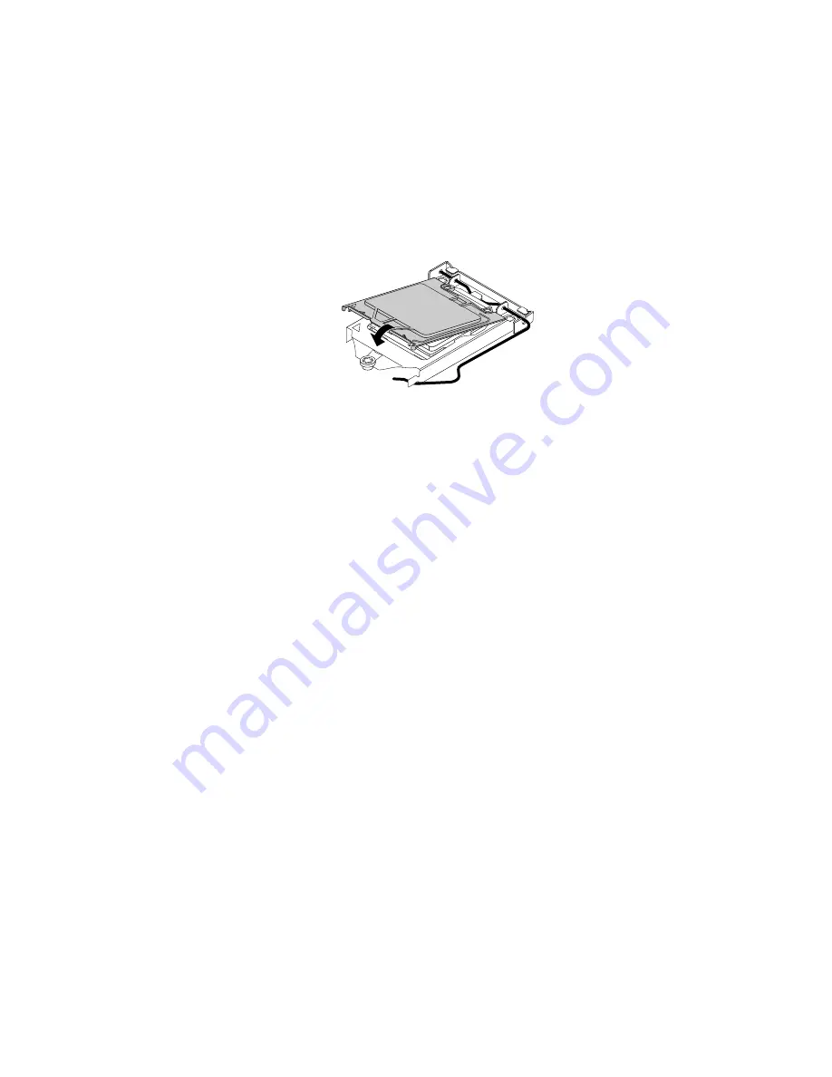
2. Note the orientation of the socket cover, and install one side of the socket cover into the microprocessor
socket. Carefully press the other side of the socket cover downward until the socket cover snaps
into position.
Note:
The microprocessor socket cover might look slightly different from the illustration.
Figure 77. Installing the microprocessor socket cover
3. Carefully check the four corners of the socket cover to ensure that the cover is seated securely.
4. Follow any additional instructions that are included with the replacement part you received.
Completing the parts replacement
After completing the installation or replacement for all parts, reinstall the computer cover and reconnect
cables. Depending on the parts you installed or replaced, you might need to confirm the updated information
in the Setup Utility program. Refer to “Using the Setup Utility program” on page 63.
To reinstall the computer cover and reconnect cables to your computer, do the following:
1. Ensure that all components have been reassembled correctly and that no tools or loose screws are
left inside your computer. See “Computer components” on page 31 for the locations of various
components in your computer.
2. Ensure that the cables are routed correctly before reinstalling the computer cover. Keep cables clear of
the hinges and sides of the computer chassis to avoid interference with reinstalling the computer cover.
3. Position the computer cover on the chassis so that the rail guides on the bottom of the computer
cover engage the rails on the chassis. Then, push the cover to the front of the computer until it snaps
into position.
.
Installing or replacing hardware
133
Содержание ThinkCentre M700
Страница 6: ...iv ThinkCentre M700 and M900 Hardware Maintenance Manual ...
Страница 8: ...vi ThinkCentre M700 and M900 Hardware Maintenance Manual ...
Страница 16: ...8 ThinkCentre M700 and M900 Hardware Maintenance Manual ...
Страница 20: ...12 ThinkCentre M700 and M900 Hardware Maintenance Manual ...
Страница 21: ...1 2 Chapter 1 Read this first Important safety information 13 ...
Страница 22: ...1 2 14 ThinkCentre M700 and M900 Hardware Maintenance Manual ...
Страница 27: ...1 2 Chapter 1 Read this first Important safety information 19 ...
Страница 28: ...1 2 20 ThinkCentre M700 and M900 Hardware Maintenance Manual ...
Страница 31: ...Chapter 1 Read this first Important safety information 23 ...
Страница 56: ...48 ThinkCentre M700 and M900 Hardware Maintenance Manual ...
Страница 64: ...56 ThinkCentre M700 and M900 Hardware Maintenance Manual ...
Страница 66: ...Figure 8 Installing a padlock 58 ThinkCentre M700 and M900 Hardware Maintenance Manual ...
Страница 70: ...62 ThinkCentre M700 and M900 Hardware Maintenance Manual ...
Страница 142: ...134 ThinkCentre M700 and M900 Hardware Maintenance Manual ...
Страница 148: ...140 ThinkCentre M700 and M900 Hardware Maintenance Manual ...
Страница 152: ...144 ThinkCentre M700 and M900 Hardware Maintenance Manual ...
Страница 156: ...148 ThinkCentre M700 and M900 Hardware Maintenance Manual ...
Страница 159: ...Appendix D China Energy Label Copyright Lenovo 2015 2016 151 ...
Страница 160: ...152 ThinkCentre M700 and M900 Hardware Maintenance Manual ...
Страница 162: ...154 ThinkCentre M700 and M900 Hardware Maintenance Manual ...
Страница 165: ......
Страница 166: ......