4
System ID button with ID LED
When you press the system ID button, the ID LEDs on both the front and rear of the storage product are lit to
help you locate the storage product among other storage products. You also can turn on the ID LEDs using a
remote management program for storage product presence detection.
Status
Color
Description
On
Blue
The system is identified.
Off
None
The ID LED is not in use or the system is not
identified.
5
DisplayPort connector
Used to attach a high-performance monitor, a direct-drive monitor, or other devices that use a DisplayPort
connector.
6
USB 2.0 connectors (2)
Used to attach a USB-compatible device, such as a USB keyboard, mouse, scanner, or printer. If you have
more than four USB devices, you can purchase a USB hub, which you can use to connect additional
USB devices.
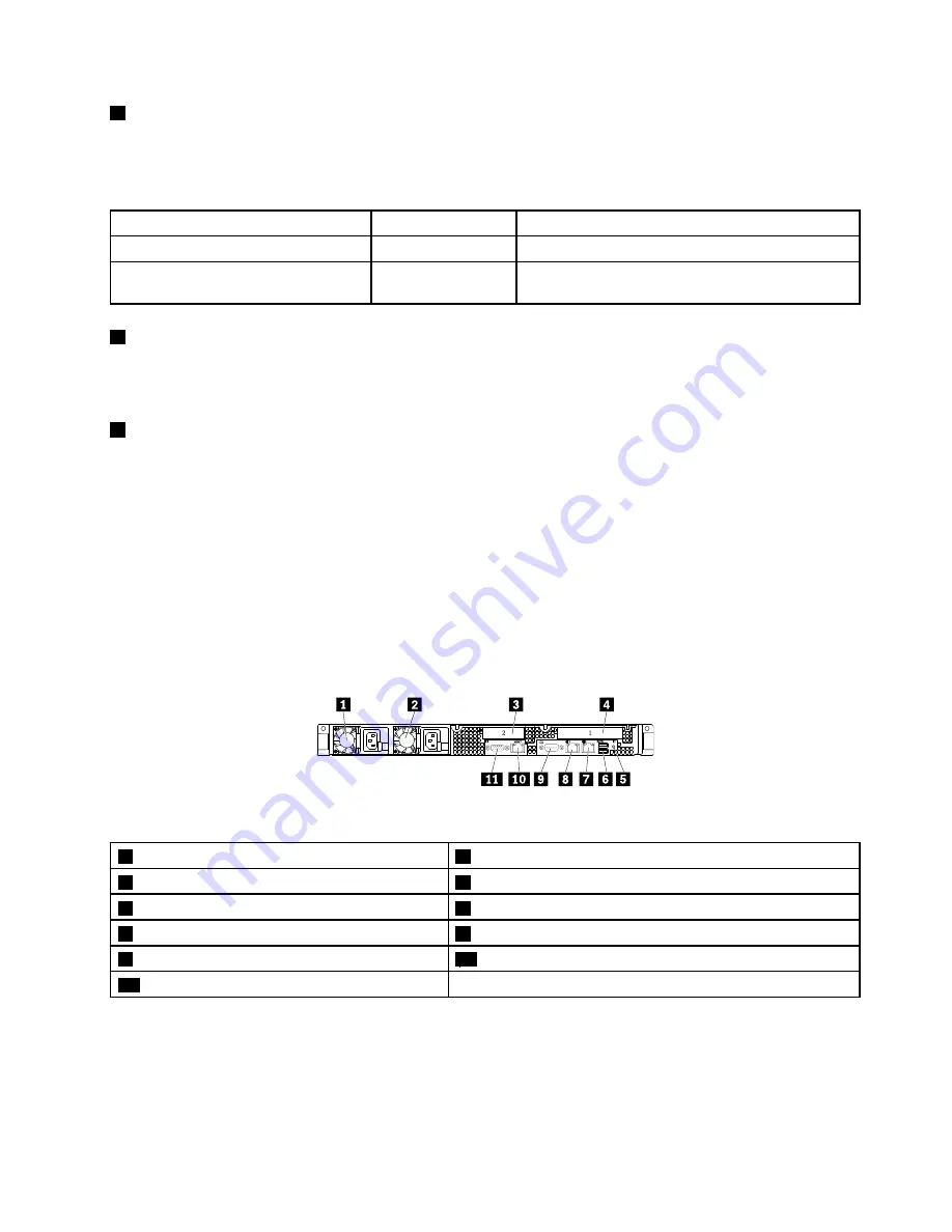
Rear view of the storage product
This topic provides information to help you locate the connectors and components on the rear of your
storage product.
The following illustration shows the connectors and components on the rear of your storage product. The
rear view of the storage product varies by model.
Figure 4. Rear view of the storage product
1
Power supply 1
2
Power supply 2 (available on some models)
3
PCIe slot 2
4
PCIe slot 1
5
System ID LED
6
USB 3.0 connectors (2)
7
Ethernet connector 2 (RJ-45)
8
Ethernet connector 1 (RJ-45)
9
Serial connector
10
Ethernet connector for system management (RJ-45)
11
VGA connector (DB-15)
17
Содержание Storage N3310
Страница 1: ...Lenovo Storage N3310 User Guide and Hardware Maintenance Manual Machine Types 70FX and 70FY ...
Страница 14: ...xii Lenovo Storage N3310 User Guide and Hardware Maintenance Manual ...
Страница 18: ...4 Lenovo Storage N3310 User Guide and Hardware Maintenance Manual ...
Страница 20: ...6 Lenovo Storage N3310 User Guide and Hardware Maintenance Manual ...
Страница 138: ...124 Lenovo Storage N3310 User Guide and Hardware Maintenance Manual ...
Страница 151: ......
Страница 152: ......


