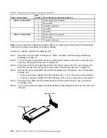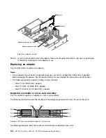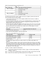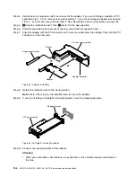
Operator information /
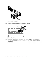
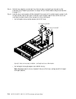
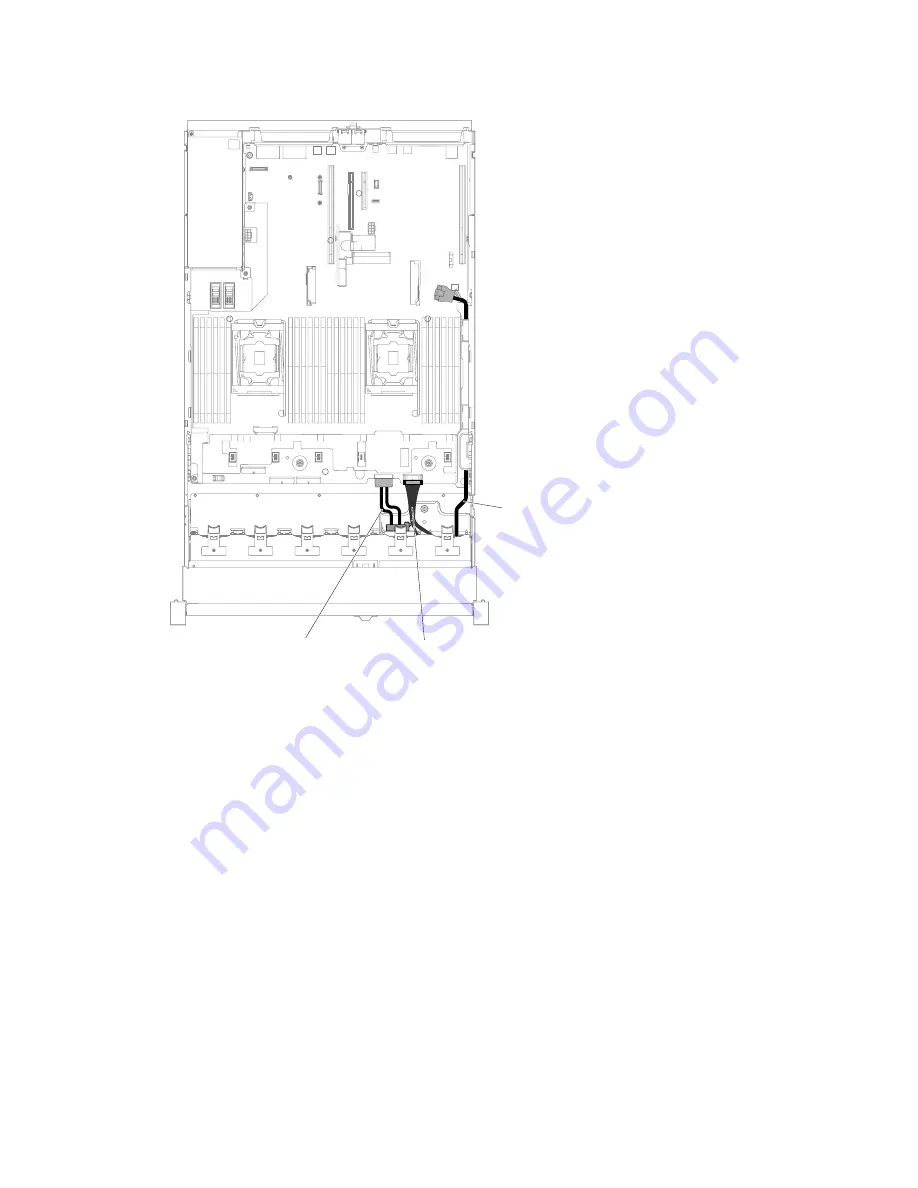
LCD panel cable
DVD drive cable
Front USB cable
Figure 72. Cable routing
Step 7.
Replace the top cover (see “Replacing the top cover” on page 118).
Step 8.
Slide the server into the rack.
Step 9.
Reconnect the power cords and any cables that you removed.
Step 10. Turn on the peripheral devices and the server.
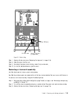
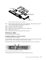
Removing a riser-card assembly
Use this information to remove a riser-card assembly.
See http://www.lenovo.com/ serverproven/ for a list of riser-card assemblies that you can use with the server.
To remove a riser-card assembly, complete the following steps:
Step 1.
Read the safety information that begins on page “Safety” on page v and “Removing and replacing
guidelines” on page 101.
Step 2.
Turn off the server and peripheral devices, and disconnect the power cord and all external cables.
Step 3.
Remove the top cover (see “Removing the top cover” on page 116).
.
Removing, and replacing components
143
Содержание HX3510-G
Страница 1: ...HX3510 G HX5510 HX5510 C HX7510 Installation and Service Guide Machine Type 8695 ...
Страница 6: ...iv HX3510 G HX5510 HX5510 C HX7510 Installation and Service Guide ...
Страница 62: ...50 HX3510 G HX5510 HX5510 C HX7510 Installation and Service Guide ...
Страница 102: ...90 HX3510 G HX5510 HX5510 C HX7510 Installation and Service Guide ...
Страница 112: ...100 HX3510 G HX5510 HX5510 C HX7510 Installation and Service Guide ...
Страница 1222: ...1210 HX3510 G HX5510 HX5510 C HX7510 Installation and Service Guide ...
Страница 1229: ...People s Republic of China Class A electronic emission statement Taiwan Class A compliance statement Appendix E Notices 1217 ...
Страница 1230: ...Taiwan BSMI RoHS declaration 1218 HX3510 G HX5510 HX5510 C HX7510 Installation and Service Guide ...
Страница 1238: ...1226 HX3510 G HX5510 HX5510 C HX7510 Installation and Service Guide ...
Страница 1239: ......
Страница 1240: ......

