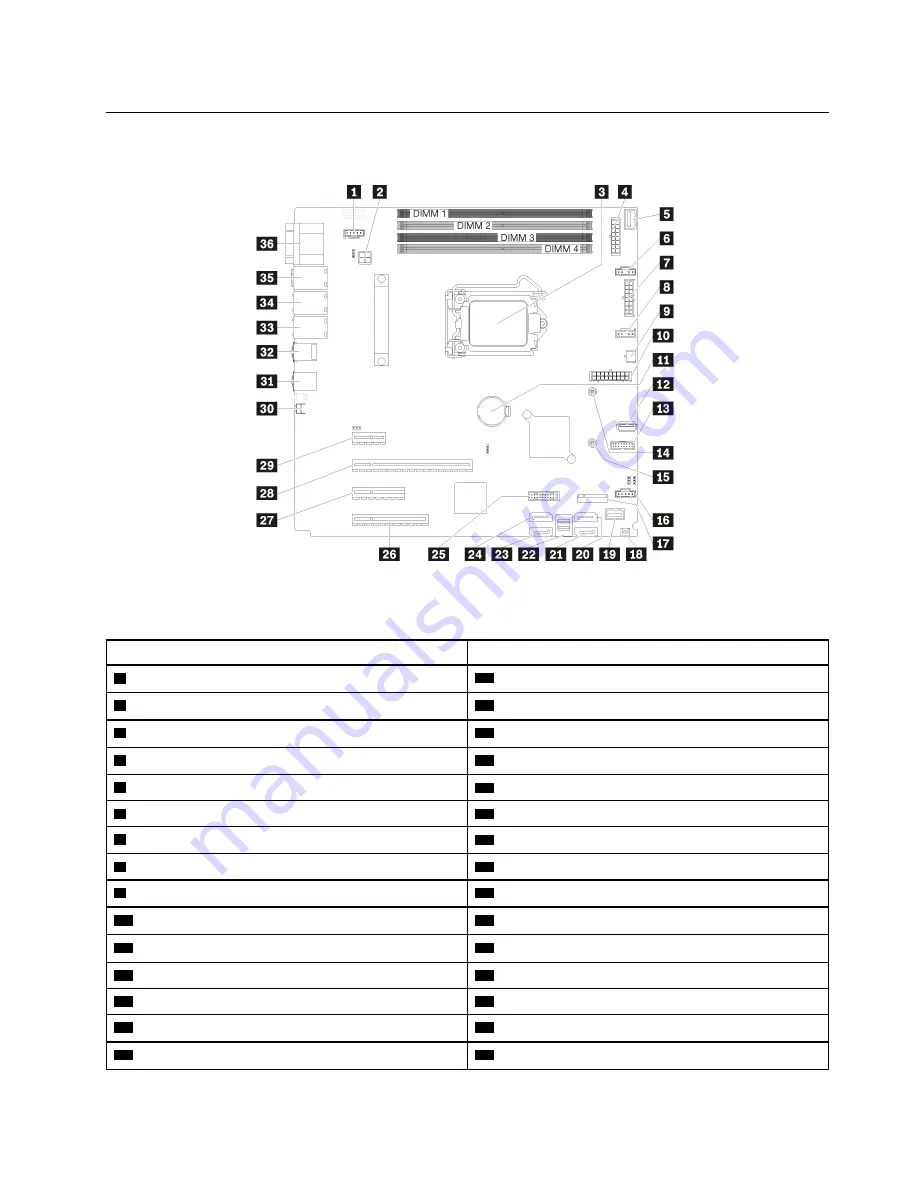
System board components
The illustration in this section shows the component locations on the system board.
Figure 13. System board components
Table 7. Components on the system board
Callout
Callout
1
Fan 3 connector for Rear FAN
19
Front panel connector
2
Processor power connector
20
SATA hard disk drive 6/optical disk drive connector 1
3
Processor
21
SATA hard disk drive 7/optical disk drive connector 2
4
Backplane 1 power connector
22
SATA hard disk drive 0–3 connector
5
PIB side band connector
23
SATA hard disk drive 4 connector
6
Fan 1 connector for Front FAN 1
24
SATA hard disk drive 5 connector
7
Backplane 2 power connector
25
Front USB 3.0 / 2.0 header
8
Fan 2 connector for CPU FAN
26
PCIe3 x8 slot 4
9
Optical drive power connector
27
PCIe3 x4 slot 3
10
System power connector
28
PCIe3 x16 slot 2
11
CMOS battery
29
PCIe3 x1 slot 1
12
Internal USB 3.1 Gen 1 connector
30
NMI button
13
TPM card connector
31
USB 3.1 Gen 1 connectors
14
Mounting nut for 80 mm M.2
32
USB 3.1 Gen 2 connectors
15
Mounting nut for 42 mm M.2
33
Ethernet 2 connector
.
27
Содержание 7Y45
Страница 1: ...ThinkSystem ST250 Setup Guide Machine Types 7Y45 and 7Y46 ...
Страница 4: ...ii ThinkSystem ST250 Setup Guide ...
Страница 18: ...14 ThinkSystem ST250 Setup Guide ...
Страница 110: ...106 ThinkSystem ST250 Setup Guide ...
Страница 112: ...108 ThinkSystem ST250 Setup Guide ...
Страница 115: ......
Страница 116: ...Part Number SP47A37787 Printed in China 1P P N SP47A37787 1PSP47A37787 ...


