Light path diagnostics
This topic provides an overview of the light path diagnostics LEDs.
Light path diagnostics is a system of LEDs on various external and internal components of the server that
leads you to the failed component. When an error occurs, LEDs are lit on the front operator panel on the front
of the of the server, then on the failed component. By viewing the LEDs in a particular order, you can often
identify the source of the error.
When LEDs are lit to indicate an error, they remain lit when the server is turned off, provided that the server is
still connected to power and the power supply is operating correctly.
Before you work inside the server to view light path diagnostics LEDs, read “Safety” on page v, “Installation
guidelines” on page 44, and “Handling static-sensitive devices” on page 46.
If an error occurs, view the light path diagnostics LEDs in the following order:
1. Look at the front operator panel (see “Front operator panel” on page 27) on the front of the server.
• If the check log LED is lit, it indicates that information about an un-isolated fault condition in the
server is available in the IMM event log or in the system-event log.
• If the system-error LED is lit, it indicates that an error has occurred; go to step 2.
Note: Reset button:
Press this button on the front operator panel to reset the server and run the power-
on self-test (POST). You might have to use a pen or the end of a straightened paper clip to press the
button.
2. The modules in the server (on the front and rear) have LEDs that are lit to indicate the location of a
problem.
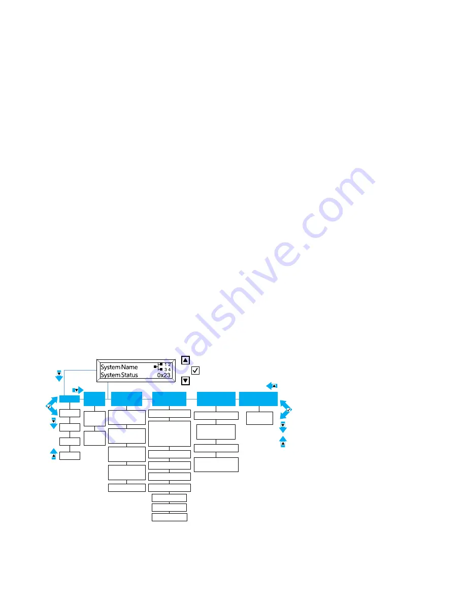
In addition to the light path diagnostic LEDs, the server LCD system information display panel also displays a
current list of errors reported by the system and other information. The following is an illustration of the LCD
display panel. See the “LCD system information display panel” on page 27 for more information about the
LCD display panel.
Errors
Error 1
Error 2
Error 3
Error n
System
VPD
MTM #
Serial #
UUID
String
pDSA Code
System
FW Levels
UEFI
Primary Level
UEFI
Backup Level
IMM Primary
Level
IMM Backup
Level
IMM Hostname
IMM
Network Info.
IMM Ext MAC
or IMM
Shared MAC
IP Add.
DNS Primary
DNS Secondary
DNS Tertiary
System
Environmental
Ambient Temp
CPU1...CPU4
Temps
Estimated Power
Consumption
AC Input Voltage
Subnet
Gateway
IPV6 Add.
Scroll Up Button
Select Button
Scroll Down Button
Actions
System
reset
For the location of the LEDs on the modules in the front of the server, see “Storage book LEDs” on page 153,
“Compute book LEDs” on page 154, and “DIMMs and microprocessor LEDs” on page 155.
152
System x3850 X6 and x3950 X6 Installation and Service Guide
Содержание 6241
Страница 1: ...System x3850 X6 and x3950 X6 Installation and Service Guide Machine Type 6241 ...
Страница 6: ...iv System x3850 X6 and x3950 X6 Installation and Service Guide ...
Страница 56: ...42 System x3850 X6 and x3950 X6 Installation and Service Guide ...
Страница 82: ...68 System x3850 X6 and x3950 X6 Installation and Service Guide ...
Страница 132: ...118 System x3850 X6 and x3950 X6 Installation and Service Guide ...
Страница 158: ...144 System x3850 X6 and x3950 X6 Installation and Service Guide ...
Страница 214: ...200 System x3850 X6 and x3950 X6 Installation and Service Guide ...
Страница 358: ...344 System x3850 X6 and x3950 X6 Installation and Service Guide ...
Страница 1938: ...1924 System x3850 X6 and x3950 X6 Installation and Service Guide ...
Страница 1964: ...1950 System x3850 X6 and x3950 X6 Installation and Service Guide ...
Страница 1968: ...1954 System x3850 X6 and x3950 X6 Installation and Service Guide ...
Страница 1975: ...Taiwan Class A compliance statement Appendix F Notices 1961 ...
Страница 1976: ...Taiwan BSMI RoHS declaration 1962 System x3850 X6 and x3950 X6 Installation and Service Guide ...
Страница 1988: ...1974 System x3850 X6 and x3950 X6 Installation and Service Guide ...
Страница 1989: ......
Страница 1990: ......


