Page 22
507994-01 11/19
Table 4. HFC-410A Temperature (°F) - Pressure (Psig)
°F
°C
Psig
°F
°C
Psig
-40
-40.0
11.6
60
15.6
170
-35
-37.2
14.9
65
18.3
185
-30
-34.4
18.5
70
21.1
201
-25
-31.7
22.5
75
23.9
217
-20
-28.9
26.9
80
26.7
235
-15
-26.1
31.7
85
29.4
254
-10
-23.3
36.8
90
32.2
274
-5
-20.6
42.5
95
35.0
295
0
-17.8
48.6
100
37.8
317
5
-15.0
55.2
105
40.6
340
10
-12.2
62.3
110
43.3
365
15
-9.4
70.0
115
46.1
391
20
-6.7
78.3
120
48.9
418
25
-3.9
87.3
125
51.7
446
30
-1.1
96.8
130
54.4
476
35
1.7
107
135
57.2
507
40
4.4
118
140
60.0
539
45
7.2
130
145
62.8
573
50
10.0
142
150
65.6
608
55
12.8
155
System Operation
IMPORTANT
Some scroll compressor have internal vacuum protector
that will unload scrolls when suction pressure goes
below 20 psig. A hissing sound will be heard when the
compressor is running unloaded. Protector will reset
when low pressure in system is raised above 40 psig. DO
NOT REPLACE COMPRESSOR.
CRANKCASE HEATER (HR1) AND THERMOSTAT
SWITCH (S40)
Compressor in models listed below are equipped with a
belly-band type crankcase heater. HR1 prevents liquid
from accumulating in the compressor. HR1 is controlled by
a single pole, single throw thermostat switch (S40) located
on the liquid line (see figure 1 for location).
When liquid line temperature drops below 50°F the
thermostat closes energizing HR1. The thermostat will
open, de-energizing HR1 once liquid line temperature
reaches 70° F.
HIGH PRESSURE SWITCH (S4)
TSA*H4 units are equipped with a high-pressure switch
that is located in the liquid line of the compressor. The
switch (SPST, manual reset, normally closed) removes
power from the compressor when discharge pressure
rises above factory setting at 590 + 10 psi
MANUAL RESET
BUTTON
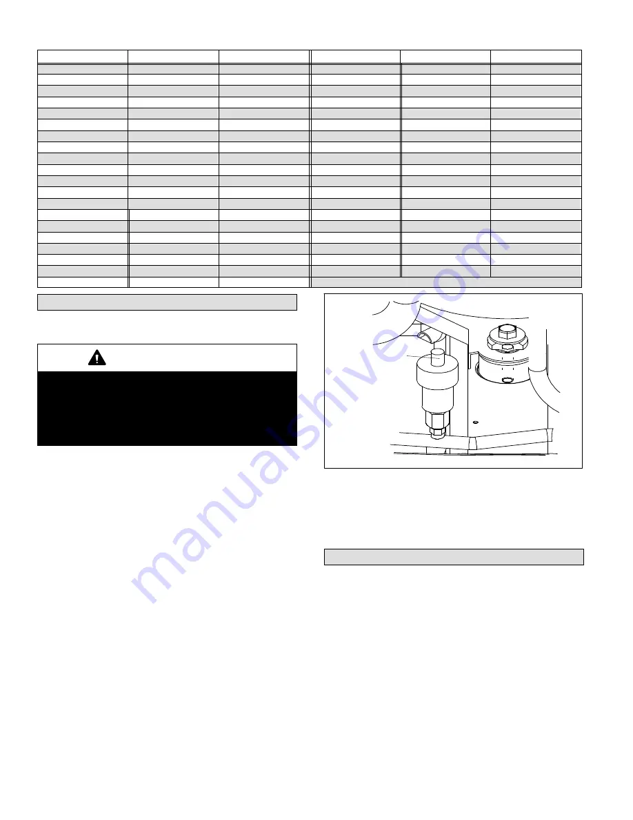
Figure 22. High Pressure Switch (S4) Manual Reset
LOW PRESSURE SWITCH (S87)
TSA*H4 units are equipped with a low pressure switch that
is located in the suction line to the compressor. The switch
is a SPST, auto-reset switch that is normally closed. The
switch opens at 25 psi and closes at 40 psi.
Maintenance
DEALER
Maintenance and service must be performed by a qualified
installer or service agency. At the beginning of each
cooling season, the system should be checked as follows:
Outdoor Unit
1. Outdoor unit fan motor is pre-lubricated and sealed.
No further lubrication is needed.
2. Visually inspect all connecting lines, joints and coils for
evidence of oil leaks.
3. Check all wiring for loose connections.
4. Check for correct voltage at unit (unit operating).
5. Check amp draw on outdoor fan motor.


