


Page 24
Oil Furnace Start−Up Checklist
(Complete this page and keep for future reference)
Customer Name
Street Address
City
State/Zip Code
Furnace Model #
Serial #
Input Rate
Nozzle Used
New Construction
Replacement
Date of Installation
Installation Data
Start−Up Procedure
Furnace Location:
A
Basement − Open
Enclosed*
B
Utility Room − Open
Enclosed*
C
Closet − Open
Enclosed*
D
Crawl Space − Open
Enclosed*
*Provisions must be made for adequate air for combustion. See
Combustion and Ventilation Air
Chimney Data:
A
Inside Outside
B
Brick
Masonry
C
Lined
Size
D
Type: Class A All purpose
Type: L
E
Condition
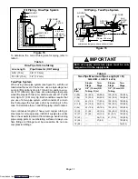
Flue Pipe:
A
Distance to Chimney
Pitch
B
Diameter
C
Barometric Damper Installed
D
Drill 5/16" hole in flue pipe 12" upstream of barometric
damper
E
Drafting Reading:
F
Adjust Barometric:
Oil Tank Data:
A
Installed in Basement
B
Installed Outside
C
Buried/Depth
D
Size
Gallons
E
Age
F
Last cleaned on date
Oil Lines:
A
Size: 3/8"
1/2"
Other
B
Single Pipe
Two Pipe
C
Distance from Tank
Lift
D
Filter Type
Inspect
Change
E
Pressure Test
F
All fittings checked for tightness
Thermostat
A
Type: Heating
Cooling
B
Anticipator Set:
C
Wires: New
Old
Air Filter
A
Filter Type: Permanent
Disposable
B
Installed:
C
Size:
A
Close disconnect switch
B
Set thermostat to call for heat
C
Bleed air from lines and pump; run for 20 seconds after bubble
disappears
D
Install vacuum gauge; check pump vacuum
E
Install pressure gauge; adjust pressure gauge to 140 psig. Al-
ways verify proper pump pressure to corresponding tables
with instructions supplied with unit.
F
After 10 minutes operating, obtain flue temperature reading:
1st
2nd
3rd
G
Obtainsmokereading:
1st
2nd
3rd
H
MeasureCO
2:
:
1st
2nd
3rd
I
Check draft overfire:
Breech
J
Air shutter setting
Locked
K
Measure static pressure in duct system:
Supply side static pressure
Return side static pressure
Static pressure drop
L
Temperature rise after steady state conditions have been
achieved: Supply side
Return side
M
Block off return air (limit control checkout); confirm burner shut
down within 2 to 3 minutes
Owner Record
Installed by:
Dealer:
Address
Telephone No. ( )
License No.
Notes:
Downloaded from


