background image

B975 User Guide

Chapter 7

  Router Table Operation

58

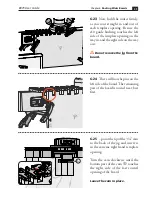
7-30

 Before clamping the first 

socket board, ensure the socket board 

stop is fully retracted, and locked in 

place.

7-31

  With the left edge of the board 

in the first template opening, position 

the socket board on the jig, leaving 

equal amounts of the board showing 

at each edge. 

Clamp the jig in place.

7-32

  Slide the socket board stop 

until it touches the edge of the board, 

and secure with the thumb lock. 

The side stop remains locked in place 

for all socket and pin board routing.

S

Содержание B975

Страница 1: ...See Page 65 for Customer Support 1 800 663 8932 User Guide Leigh Router Joinery Jigs Router Table Workbench Leigh Box Joint Beehive Jig Model B975 For WorkBench or Router Table Use ...

Страница 2: ...Leigh Box Joint Beehive Jig Model B975 is a simple easy to use tool for making 1 2 and 3 4 box joints on boards up to 13 16 20 6mm thick and from 1 1 2 38mm to 17 13 16 453mm wide Not by accident the full 9 11 16 246mm width of the jig is the standard height of a typical beehive super used in North America Customer Support If you have any questions that are not answered in this user guide please c...

Страница 3: ...al distributor in the region of the winner No cash value Value is in the currency of the country of winner equal to 300 00 USD based on currency exchange at the time of the draw Complete details available at www leighjigs com Register your Leigh B975 Register Now for Your Chance to Privacy Policy Leigh will NEVER rent sell or distribute your information Be the first to learn new ways to use your j...

Страница 4: ...B975 User Guide 4 This page is left blank intentionally ...

Страница 5: ...TITY A Jig Template with Decal 313503 1 Bag 1 B Side Stop Assembly 1 2 313530 1 C Side Stop Assembly 3 4 313535 1 D Step over Cam with O ring 1 2 313550 1 E Step over Cam with O ring 3 4 313555 1 Bag 2 F Pan Head Wood Screws No 8 x 1 313585 10 G Guide Bushing e10 eBush e10 1 H Straight Bit 1 2 160 1 I Pin Wrench 730V 1 Bag 3 J Fully Illustrated User Guide 313565 1 K Instructional DVD 313570 1 What...

Страница 6: ...er 1 Introduction 6 1 2 Bit e10 eBush Clamps User Supplied Step over Cam 3 4 Step overCam1 2 MDF Beam User Made Side Stop Template Router User Supplied Leigh Box Joint Beehive Jig Thumb Lock Pin Board and Socket Board Stops ...

Страница 7: ...Beehive Jig Your new jig is shipped with a 1 2 2 flute carbide tipped straight bit You may also use a 1 2 spiral up cut bit in high speed steel or solid carbide E 160 bit comes with the Beehive Box Joint Jig Optional spiral up cut bits rout cleaner and faster leaving a smoother finish A C B D E A C Units of Measure IMPORTANT INCHES AND MILLIMETERS Text and illustrations in this English language us...

Страница 8: ...This board edge against the side stop on other side of the board hidden from view Box Assembly Assemble the box keeping the marked edges of the boards together as shown Clamping Note Before mounting and routing the boards you should mark them with the appropriate symbols With box joints the same board edgeA always goes against the side stop Boards are clamped against the beam both face in and face...

Страница 9: ...not optional Read and follow the recommendations here Never drink alcohol or take medications that can cause drowsiness while operating a router Read the owner s manual that came with your router and router table It is essential to understand all manufacturer s instructions completely B975 User Guide CHAPTER 2 Safety ...

Страница 10: ...outer to the power source make sure the bit and collet revolve freely with and without the guide bushing in place After routing wait for the bit to come to a complete stop before removing the router from the jig Never rout at face level Chips and sawdust are thrown out at high speed Do not tilt the router Keep the router flat on the jig during all routing ...

Страница 11: ... with the included e10 eBush guide bushing The e10 is installed in the base of the router and the guide bushing retaining nut is screwed on under the router base Patents for Leigh elliptical guide bushings U S 9 375 860 UK GB2443974 Note Normal tolerances with bits guide bushings and router runout will generally produce poor fitting joints The included Leigh e10 elliptical guide bushing eBush solv...

Страница 12: ...h eBush barrel A is elliptical unlike plain circular template guide bushings B When the e10 is rotated the effective diameter of the barrel changes allowing fit adjustments as small as 0 001 0 025mm The e10 eBush is included with the jig B A 3 3 The Leigh eBush System is designed around the 1 3 8 industry standard Some routers accept the Leigh eBush directly Many routers require the use of a guide...

Страница 13: ...20 0 5mm 5 8 0 010 0 010 3 7 One increment of the eBush changes the joint glue line by 0 002 0 05mm Half an increment changes the fit by an incredible 0 001 0 025mm A perfect fit will be established with one or two test cuts 3 8 Each chapter provides a place to mark your perfect eBush setting for easy repeatability the next time May 5 3 4 joint Walnut 160 bit Feb 28 1 2 joint Maple 160 bit EXAMPLE...

Страница 14: ...sure to retighten the eBush nut after each adjustment 3 10 Make a small scratch line on the router base or eBush adapter at the 12 o clock position This will be a reference line for all eBush settings A 3 9 Fitting the eBush to the Router Place the router on the jig with handles positioned the way you would normally hold the router A Then turn the router upside down and place it on the workbench B...

Страница 15: ...he Leigh B975 You will need A workbench with vice or a portable workbench 2 pieces of 3 4 MDF to make a beam 1 1 2 x 3 1 2 x 16 38mm x 90mm x 406mm Router with 1 2 collet Electric drill preferably bench or pedestal but handheld will work 1 8 drill bit Two Quick Grip clamps Square ruler or tape measure No 2 Phillips screwdriver Wood Glue ...

Страница 16: ...ate will be attached to the top of the beam so be sure the top edges are flush and free of glue residue Set aside to dry completely Alternatively a common 2x4 may be used See step 4 15 for special instructions 4 3 The 1 2 comb has position ing ridges A molded into the bottom side of the template A 4 2 One side of the template is used for 3 4 box joints and the other side is used for 1 2 joints ...

Страница 17: ...forward until the ridges on the underside of the 1 2 comb contact the back of the beam The template is now positioned correctly 4 5 Use a pencil and mark the location of all screw holes on the top of the template Hold the template in place and proceed to the next step 4 6 Make a pencil line on the top of the beam at each end of the jig on the 3 4 and 1 2 sides ...

Страница 18: ...am facing up Use a square and draw a vertical line down from the positioning mark on the top of the beam 4 9 Next draw a horizontal line 1 down from the top of the beam Rotate the beam and repeat for the 3 4 side 4 7 Remove the template and mark 3 4 and 1 2 beside the lines to indicate which is the 3 4 and which is the 1 2 side of the beam 1 3 4 1 2 1 2 1 2 ...

Страница 19: ...k down to lock it in place Position it against the layout lines as shown Use a pencil to mark the screw hole locations Rotate the beam and repeat the process for the 1 2 side 4 12 Use a drill press or hand drill with a 1 8 bit to drill pilot holes at all screw hole locations 4 10 The 3 4 and 1 2 side stops will be attached in the following steps 3 4 Side Stop 1 2 Side Stop 3 4 ...

Страница 20: ...ines with the thumb lock facing the left end of the beam and attach it using the included screws Again use a screwdriver not a power drill to attach the side stop Repeat the process with the 1 2 side stop on the 1 2 side of the beam 4 13 Clamp the beam in the vice with its 3 4 side facing you Position the template on the beam with the 3 4 side of the template facing you Align it with the pre drill...

Страница 21: ... in all template openings on both sides of the beam as shown in the following steps Preparing the beam is particularly important when using a common 2x4 because its side grain will tear out badly 4 17 Install the Bit Install the No 160 1 2 straight bit or equivalent in the router The bit goes through the guide bushing and fits in the router collet Tighten the collet and rotate the bit and collet t...

Страница 22: ...1 Place the router on the jig and adjust the tip of the bit up or down until it s at the center of the line Rotate the bit and collet to ensure it spins freely and does not contact the eBush 4 19 Depth of Cut Select a board at least 9 3 4 248mm wide and 1 2 to 3 4 thick Length is not important as long as it can be clamped safely in the vice Set the depth of cut by marking a line 3 4 from the top e...

Страница 23: ...mplate opening Be sure the guide bushing touches the left side of each template opening on the way in and the right side on the way out Use the other end of the board and repeat for the 1 2 side of the jig 4 23 There will now be a clean groove in each template opening on both sides of the beam The beam and jig are now ready to use ...

Страница 24: ...24 B975 User Guide Chapter 4 Mounting Assembly This page is left blank intentionally ...

Страница 25: ...ion may be used Maximum board thickness for both joint sizes is 13 16 20 6mm Depth of cut can be increased beyond the board thickness for raised joints Note Optional 1 2 diameter spiral upcut bits may also be used 1 2 1 2 1 4 3 4 0 13 16 160 180 Depth of Cut Item No Carbide Tipped Bit Diameter Item No Spiral HSS Optional Item No Spiral Solid Carbide Optional 180C Bit Cutting Depth 160 included e10...

Страница 26: ...ered in Chapter 6 Symmetrical Board Widths for 3 4 Box Joints Total Pins Sockets 3 5 7 9 11 13 Inches 2 3 16 3 11 16 5 3 16 6 11 16 8 3 16 9 11 16 Millimeters 56 94 132 170 208 246 Asymmetrical Board Widths for 1 2 Box Joints Total Pins Sockets 4 6 8 10 12 14 16 18 Inches 1 15 16 3 4 5 1 16 6 1 16 7 1 16 8 1 8 9 1 8 Millimeters 50 76 102 128 154 180 206 232 Asymmetrical Board Widths for 3 4 Box Jo...

Страница 27: ...hicknesses may also be joined Symmetrical Asymmetrical Full size pins and sockets Full size pins and sockets When a symmetrical board width is reduced the joint will have smaller but equal sized pins and sockets at each edge of the board Width specified in the board width chart results in full size pins and sockets at each edge of the board Width specified in the board width chart results in a ful...

Страница 28: ...rk a line on the board indicating depth of cut 5 7 Routing a Test Fit Joint Test joints are always routed with the eBush set at the 5 position Retighten the eBush nut after each guide bushing adjustment 5 8 Clamp one of the test boards in the vice Using the 3 4 side of the jig position the left end of the jig over the test board and clamp in place Board alignment is not important when routing a te...

Страница 29: ...the left side of the template opening on the way in and the right side on the way out Do not rotate the router 5 12 Remove the jig from the first test board and repeat the process for the second test board 5 10 Place the router on the jig and adjust the tip of the bit up or down until it s at the center of the line Rotate the bit and collet to ensure it spins freely and does not contact the eBush ...

Страница 30: ... joint is too loose use the pin wrench and turn the eBush to a higher number and rout two fresh board ends If the joint is too tight turn the eBush to a lower number and rout two fresh board ends One or two test cuts should produce a perfect fit 5 15 Use these eBush diagrams to record the settings you used to achieve perfect joint fit The first eBush is simply an example of how to record your sett...

Страница 31: ... four boards for the box Mark an S socket board on two of the boards and a P pin board on two boards Also mark the common board edges that will go against the side stop These edges will align at the top or bottom edge of the box when assembled A B 5 18 Side Stop Positions The side stop is used to position the pin and socket boards Put the socket board stop in the S position Afor all socket boards ...

Страница 32: ...he first template opening position thejig over the socket board leaving equal amounts of the board showing at each edge Clamp the jig in place 5 21 Asymmetrical Joints Clamp the first socket board in the vice With the left edge of the board in the first template opening position the jig over the socket board Note Asymmetrical boards cannot be centered under the template With the side stop fully re...

Страница 33: ...nd pin board routing 5 23 Socket and pin boards can be different thicknesses Always use the mating pin or socket board to determine depth of cut In this case hold the pin board flush under the template and draw a line on the socket board indicating depth of cut 5 24 Place the router on the jig and adjust the tip of the bit up or down until it s at the center of the line Rotate the bit and collet t...

Страница 34: ...eep the router handles parallel to the jig while routing 5 26 There will now be a full socket at each edge of the socket board Turn the socket board end for end keeping the same board edge against the side stop Rout the other end of the board Repeat for the second socket board and remove the jig from the socket board S 5 27 Routing the Pin Board The pin board must be offset relative to the socket ...

Страница 35: ... boards are the same thickness the depth is already set 5 30 Place the router on the jig and adjust the tip of the bit up or down until it s at the center of the line P P 5 28 With the side stop set position the jig over the pin board and slide it over until the side stop touches the board edge Clamp in place P ...

Страница 36: ...de stop and rout the other end of the board Repeat for the second pin board 5 33 Assemble the box keeping the marked board edges aligned P P P S S 5 31 Hold the router firmly as you rout straight in and out of each template opening Be sure the e10 guide bushing touches the left side of the template opening on the way in and the right side on the way out Do not rotate the router P ...

Страница 37: ... with the included Leigh No 160 1 2 straight bit and the Leigh e10 guide bushing eBush No other bit diameter and guide bushing combination may be used Maximum board thickness for both joint sizes is 13 16 20 6mm Depth of cut can be increased beyond the board thickness for raised joints Note Optional 1 2 diameter spiral upcut bits may also be used P 1 2 1 2 1 4 3 4 0 13 16 160 180 Depth of Cut Item...

Страница 38: ...tal Pins Sockets 3 5 7 9 11 13 15 17 19 21 23 Inches 2 3 16 3 11 16 5 3 16 6 11 16 8 3 16 9 11 16 11 3 16 12 11 16 14 3 16 15 11 16 17 3 16 Millimeters 56 94 132 170 208 246 284 322 360 398 437 Symmetrical Board Widths for 1 2 Box Joints on Wider Boards Total Pins Sockets 3 5 7 9 11 13 15 17 19 21 23 25 27 29 31 33 35 Inches 17 16 21 2 31 2 41 2 59 16 69 16 75 8 85 8 95 8 1011 16 1111 16 1211 16 1...

Страница 39: ...5 17 19 21 23 Inches 2 3 16 3 11 16 5 3 16 6 11 16 8 3 16 9 11 16 11 3 16 12 11 16 14 3 16 15 11 16 17 3 16 Millimeters 56 94 132 170 208 246 284 322 360 398 437 6 6 Boards wider than 9 11 16 246mm cannot be centered under the template Therefore a narrower board must be used to position the sidestop Selectanarrowboardwidth from the chart and cut a boardto that width in this case 3 11 16 94mm S P 6...

Страница 40: ...ottom S 4 3 4 5 3 16 Symmetrical Board Widths for 3 4 Box Joints on Wider Boards Total Pins Sockets 3 5 7 9 11 13 15 17 19 21 23 Inches 2 3 16 3 11 16 5 3 16 6 11 16 8 3 16 9 11 16 11 3 16 12 11 16 14 3 16 15 11 16 17 3 16 Millimeters 56 94 132 170 208 246 284 322 360 398 437 6 9 Boards Widths Less Than the Chart Width For example If the chart width is 17 3 16 437mm and your board width is 16 3 4 ...

Страница 41: ...r on the jig and adjust the tip of the bit up or down until it s at the center of the line Rotate the bit and collet to ensure it spins freely and does not contact the eBush 6 13 Now hold the router firmly as you rout straight in and out of all template openings Do not rotate the router Be sure the e10 touches the left side of the template opening on the way in and the right side on the way out Do...

Страница 42: ...d The remaining part of the board is routed next but first 6 15 point the tip of the 3 4 cam tothebackofthejigandinsertitinthe extreme right hand template opening 6 16 Turn the cam clockwise until the bottom part of the cam A touches the right side of the last routed opening of the board Leave the cam in place S ...

Страница 43: ...ig in place making sure the right hand clamp will not interfere with the router Remove the cam 6 18 Rout the remaining part of the socket board Remove the jig from the board and unclamp the board from the vice 6 19 To rout the other end of the socket board turn the board horizontally and flip it end for end and re clamp in the vice Place the jig on the board with the side stop against the left boa...

Страница 44: ... stop Clamp the board in place 6 21 Socket and pin boards can be different thicknesses Hold a board of the same thickness as the socket board flush under the template and draw a line on the socket board to indicate depth of cut 6 22 Place the router on the jig and adjust the tip of the bit up or down until it s at the center of the line Rotate the bit and collet to ensure it spins freely and does ...

Страница 45: ...ight side on the way out Do not remove the jig from the board 6 24 There will now be pins on the left side of the board The remaining part of the board is routed next but first 6 25 point the tip of the 3 4 cam to the back of the jig and insert it in the extreme right hand template opening Turn the cam clockwise until the bottom part of the cam A touches the right side of the last routed opening o...

Страница 46: ...ge of the cam just touching the inside right edge Aof the last routed opening of the pin board Clamp the jig in place Rout the rest of the pin board 6 27 Remove the jig and unclamp the board from the vice To rout the other end of the pin board turn the board horizontally and flip it end for end and re clamp Place the jig on the board with the side stop against the left board edge If you re making ...

Страница 47: ...s example uses 3 4 box joints on 3 4 thick boards Procedures for routing 1 2 and 3 4 joints are identical 7 2 Parts Required 3 4 and 1 2 box joints are routed with the included Leigh No 160 1 2 straight bit and the Leigh e10 guide bushing eBush No other bit diameter and guide bushing combination may be used Maximum board thickness for both joint sizes is 13 16 20 6mm Depth of cut can be increased ...

Страница 48: ...s guide bushings are designed around the 1 3 8 diameter industry standard See specifications below Leigh eBush and Nut Router Table eBush Insert Ring Insert Plate 7 4 Insert Ring To install the eBush to your router table insert plate you may need a 1 3 8 diameter counter bore insert ring Check with your router table or insert plate router lift manufacturer as to what adaptation if any is required ...

Страница 49: ...A B 7 5 Draw a reference line with a permament pen on the router table centered on the guide bushing opening at 12 o clock and 6 o clock shown in red for clarity only This will ensure correct orientation of the eBush to the insert ring A the insert plate B and the router table C 7 7 eBush adjustments are made with the included pin wrench Markings on the eBush indicate which way to turn it for a lo...

Страница 50: ...with screws The handles will keep your fingers safely away from the bit and help control the jig during routing 7 9 With the router unplugged install the No 160 straight bit to the router and tighten the collet nut Be sure the bit spins freely within the guide bushing before reconnecting the power 7 10 Reminder If you haven t already done so you must rout grooves on each side of the beam see Chapt...

Страница 51: ...e jig parallel to the router table and go straight in and straight out of each template opening 7 12 Never tilt the jig Keep the jig flat on the router table at all times 7 13 Chips and sawdust are thrown out at high speed Always stand and use the jig away from chip and sawdust ejection Operator s Position ...

Страница 52: ...Joints Total Pins Sockets 3 5 7 9 11 13 Inches 2 3 16 3 11 16 5 3 16 6 11 16 8 3 16 9 11 16 Millimeters 56 94 132 170 208 246 Asymmetrical Board Widths for 1 2 Box Joints Total Pins Sockets 4 6 8 10 12 14 16 18 Inches 1 15 16 3 4 5 1 16 6 1 16 7 1 16 8 1 8 9 1 8 Millimeters 50 76 102 128 154 180 206 232 Asymmetrical Board Widths for 3 4 Box Joints Total Pins Sockets 4 6 8 10 12 Inches 2 15 16 4 7 ...

Страница 53: ...ter before routing any boards Symmetrical Asymmetrical Full size pins and sockets Full size pins and sockets When a symmetrical board width is reduced the joint will have smaller but equal sized pins and sockets at each edge of the board Width specified in the board width chart results in full size pins and sockets at each edge of the board Width specified in the board width chart results in a ful...

Страница 54: ... 5 position Tighten the eBush nut after each guide bushing adjustment 7 19 Center a test board on the left side of the 3 4 template leaving an equal amount overhang on each edge of the board Clamp the board in place 7 20 Slide the socket board stop until it touches the edge of the board Secure the side stop with the thumb lock ...

Страница 55: ...he jig and adjust the tip of the bit up or down until it s at the center of the line Rotate the bit and collet to ensure it spins freely and does not contact the eBush 7 23 Rout straight in and out of each template opening Be sure the e10 guide bushing touches the left side of each template opening on the way in and the right side on the way out Do not rotate the jig Chips and sawdust can accumula...

Страница 56: ...ent Assemble the test boards If the joint is too loose use the pin wrench and turn the eBush to a higher number and rout two fresh board ends If the joint is too tight turn the eBush to a lower number and rout two fresh board ends Re tighten the eBush nut after each guide bushing adjustment 7 26 Each increment on the eBush changes the joint glue line fit by 0 002 0 05mm Half an increment a mere 0 ...

Страница 57: ...termined by the depth of cut If the joint is over flush lower the bit to make a shallower cut If the joint is under flush raise the bit to make a deeper cut Rout new test joints until fit and flushness are perfect before routing the final boards 7 29 Making a Box Lay out the four boards and mark two pin boards and two socket boards Also indicate the common board edges that will go against the side...

Страница 58: ...e 7 31 With the left edge of the board in the first template opening position the socket board on the jig leaving equal amounts of the board showing at each edge Clamp the jig in place 7 32 Slide the socket board stop until it touches the edge of the board and secure with the thumb lock The side stop remains locked in place for all socket and pin board routing S ...

Страница 59: ...e left side of the template opening on the way in and the right side on the way out Do not rotate the jig There will now be a full socket at each edge of the board 7 33 Hold a pin board flush against the template and draw a line on the board indicating depth of cut 7 34 Adjust the tip of the bit up or down until it s at the center of the line S S ...

Страница 60: ...e same board edge against the side stop and clamp in place Rout in each template opening Repeat the procedure for the second socket board 7 37 Routing the Pin Board Flip the side stop to the pin board stop position 7 38 Place the first pin board on the jig with its edge touching the pin board stop and clamp in place S P ...

Страница 61: ...side of the template opening on the way in and the right side on the way out Do not rotate the jig There will now be a full pin at each edge of the board 7 40 Adjust the tip of the bit up or down until it s at the center of the line 7 39 Hold a socket board flush against the template and draw a line on the board indicating depth of cut P P ...

Страница 62: ...om the jig and assemble the joint keeping the marked board edges aligned 7 42 Unclamp and flip the first pin board end for end keeping the same board edge against the side stop and clamp in place Rout in each template opening Repeat the procedure for the second pin board P S P ...

Страница 63: ...a router fitted with the e10 guide bushing and possibly an adapter to fit the bushing to the router Leigh offers the following guide bushing adapters that fit many common routers See the list of routers in the chart on the next page For a complete list of routers see www leighjigs com FOR HAND HELD ROUTERS ONLY B975 User Guide CHAPTER 8 Guide Bushing Adapter Selection ...

Страница 64: ...00 FT2200 FT3000 721 e10 HITACHI TR8 TR12 FM8 M8 M12 Series 325211 OR 703 e10 M12VC KM12SC KM12VC Not Required e10 M12SA2 M12V2 325224 e10 MAKITA M363 MRP090 RP1800 F RP1801 F RP2300 FC RP2301 FC 3612C Europe Qk Fit Base 721 e10 3600 3606 3608 3612 3612B 3612BR 3612C N America 3620 3621 RP0900 RP900K 703 e10 3601B 321 493 1 e10 RP0910 RP1110C 706R e10 RF1100 RF1101 RD1100 RD1101 RP1101 Not Require...

Страница 65: ...gs com Technical Support help leighjigs com Website www leighjigs com Manufacturer Canada USA NOTE Email can be useful but technical queries usually raise queries from us A phone call is the quickest and most convenient way to get queries answered either directly to Leigh toll free in North America or to your national distributor Thanks TEL FAX Customer Service and Technical Support 800 663 8932 C...

Страница 66: ...w off co jp KOREA Leigh Korea 665 3 Munhyung Ri Opo Eup Kwangju Si 12774 South Korea Tel 82 0 70 8252 0988 Fax 82 0 31 765 5602 Email maengha leigh co kr Web www leigh co kr NETHERLANDS BELGIUM LUXEMBOURG Houtbewerking Krielaart 9217RR Nijega Netherlands Tel 31 512 354 770 Email gerard gkrielaart nl Web www leighjigs nl RUSSIA Unicom Ltd Nikitskij Boulevard 12 Moscow 119019 Russia Tel 7 495 690 04...

Страница 67: ...ge is to be prepaid and insured to Leigh Industries Ltd Return shipping is by means chosen by Leigh Industries Ltd for a period of five years from the date of purchase Failure resulting from alteration modification misuse abuse or neglect or after repairs have been attempted or made by others will result in no coverage The scope of this warranty is limited This warran ty constitutes the sole and e...

Страница 68: ...2 31 2 41 2 59 16 69 16 75 8 85 8 95 8 1011 16 1111 16 1211 16 133 4 143 4 153 4 1613 16 1713 16 Millimeters 37 63 89 115 141 167 193 219 245 271 297 323 349 375 401 427 453 Note Wider boards are not possible when using a router table Symmetrical Board Widths for 3 4 Box Joints Total Pins Sockets 3 5 7 9 11 13 Inches 2 3 16 3 11 16 5 3 16 6 11 16 8 3 16 9 11 16 Millimeters 56 94 132 170 208 246 As...

Отзывы: