B975 User Guide
Chapter 7
Router Table Operation
49
A
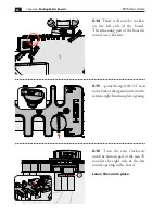
7-6
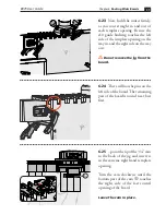
Install the e10 guide bushing
in the router table. Turn the e10 to
align the 5 position with the line
A
you’ve just drawn.
Using an initial setting of 5 allows
adjustment for a looser or tighter
joint fit. This line will also help you
guide the jig.
C
A
B
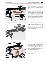
7-5
Draw a reference line with a
permament pen on the router table,
centered on the guide bushing
opening at 12 o’clock and 6 o’clock
(shown in red for clarity only).
This will ensure correct orientation
of the eBush to the insert ring
A
,
the insert plate
B
, and the router
table
C
.
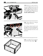
7-7
eBush adjustments are made
with the included pin wrench.
Markings on the eBush indicate
which way to turn it for a looser or
tighter fit. See Chapter 3.
Remember, every time you adjust
the eBush you must re-tighten the
eBush nut.


