ProVision 3 Installation Manual
8100-35521-00
Rev. A1
Leidos Security Detection & Automation, Inc.
–
Proprietary
Page 31 of 119
© 2020 Leidos. All rights reserved
7.0 Removal from Scanner Crate
1.
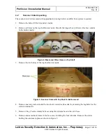
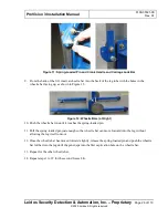
Attach each of the two ramps (2800-20769-00) to the crate using two 2½-in. PFH drywall screws
[0200-10176-40] in the outer screw holes per ramp, as shown in the following figure, ensuring that
the ramps are the proper width apart to accommodate offloading the upper/lower frame assembly.
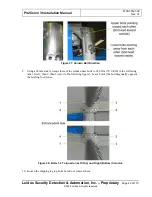
Figure 20: Ramps Attached
2.
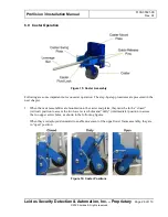
Attach the first of two caster end plates to the upper/lower frame assembly as shown in the following
figure using four M10 x 25 FHC screws (0201-20444-25) horizontally and three M8 x 20 FHC
screws [0201-20452-20] vertically. After all screws have been started, tighten the four horizontal
screws first, then the three vertical screws.
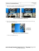
Figure 21: Caster End Plate Installation
3.
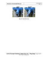
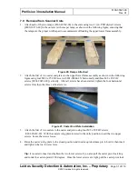
Attach the first of two casters to the caster end plate using four M8 x 20 FHC screws
(0201-20452-20). With the caster swing plate lowered to the dolly position, insert the two upper
screws. Leave the screws loose.
4.
Raise the caster swing plate to the closed position and insert a quick-release pin to hold it, then insert
and tighten the two lower screws.
Tip:
It is easier to insert and tighten the two lower screws if you also pull the caster pivot lock ring
and rotate the caster upward 180 degrees. Once the lower screws are tight, pull the caster pivot lock

