


63
General Guide to RoadPlus - 4.0.0en
Staking a Road Alignment
Pressing this key gives the difference between the designed
coordinates and staked coordinates of the point. If the point
elevation has been changed before staking, the value Diff Cut
/ Fill is calculated relative to this new elevation.
STORE (F1)
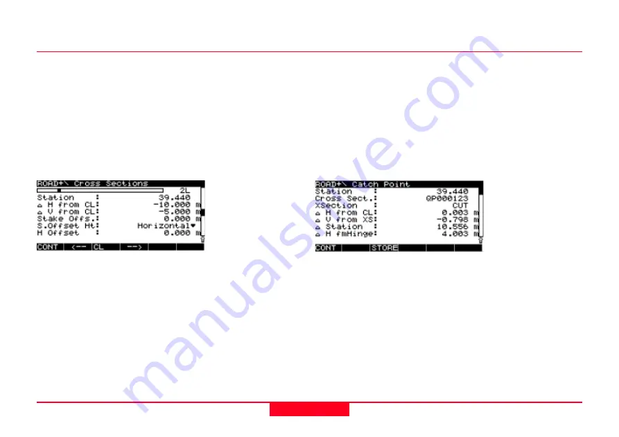
Panel ROAD+ \ Cross Sections
Here, the next point along the cross section is set for staking
out.
After staking out the last point of a cross section, the program
goes automatical to
panel ROAD+ \ Station & Offset
and
displays the next following horizontal alignment station. Start
staking its cross section with
XSEC (F4).
For complete information on how to use STAKE-OUT please
refer to chapter "Real-Time Rover, Staking Out" in the "Techni-
cal Reference Manual".
Staking a Catch Point
The stakeout functionallity for a catch point can be accessed
from the
panel ROAD+ \ Cross Sections
.
On how to get there follow the instructions in chapter Staking
a Cross Section.
Panel ROAD+ \ Cross Section
SHIFT + CATCH (F3)
Panel ROAD+ \ Catch Point
Station -
The selected station of the horizontal alignment for
which the cross section has to be staked.
Cross Sect. -
Name of the cross section template currently in
use.
XSection -
Cross section type either
CUT
or
FILL
.
∆∆∆∆∆
H from CL -
The horizontal distance of the actual pole.
position from the centre line.
∆
∆
∆
∆
∆
V from XS -
The vertical distance of the actual pole position
from the cross section template.
∆∆∆∆∆
Station -
The horizontal difference between the actual pole
position and the selected station of the horizontal alignment


