Page 146
Job Editor
Group 8
Release 2.02
JET3 Series
7.3.2 Hydraulik settings
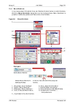
Figure 60
Hydraulic settings
1
–
Drop-down menu <Settings>
9
–
Input field <Oscillator Voltage [V]>
2
–
Option <Hydraulic settings>
10
–
Input field <Ink number>
3
–
Dialog box <Hydraulic settings>
11
–
Input field <Solvent number>
4
–
Input field <Pressure [mbar]>
12
–
Input field <Frequency [kHz]>
5
–
Input field <Suction pump [%]>
13
–
Indicators for current values
6
–
Input field <Visco correction>
14
–
Spin buttons for settings
7
–
Input field <Fall time [msec]>
15
–
Drop-down list <Ink number>
8
–
Input field <Nozzle [µ]> size
16
–
Drop-down list <Frequencies>
Warning
All settings in the
<Hydraulic>
menu have a direct impact on the functionality
of the printer!
Wrong or inappropriate settings may cause the printer to stop the work
and /or may lead to hardware damages!
All values were set at factory for an optimal operation. Changes must only be
carried out by LEIBINGER service technicians or staff trained by LEIBINGER
service technicians.
1
2
4
6
5
3
7
8
9
12
10
11
14
13
15
16
Содержание JET3
Страница 1: ...Operating Manual V2 02 Please keep for future reference ...
Страница 2: ......
Страница 21: ...Group 2 Safety Page 19 JET3 Series Release 2 02 2 4 Safety sticker Figure 1 Safety sticker Safety sticker ...
Страница 380: ...Page 378 Appendix Connection Examples for the Interfaces Group 12 Release 2 02 JET3 Series Interface X3 Outputs ...
Страница 390: ...Page 388 Appendix List of illustrations Group 12 Release 2 02 JET3 Series 12 4 2 Print head SK 6 ...
Страница 391: ...Group 12 Appendix List of illustrations Page 389 JET3 Series Release 2 02 12 4 3 Print head SK 4 Option ...
Страница 392: ...Page 390 Appendix List of illustrations Group 12 Release 2 02 JET3 Series 12 4 4 Cabinet JET printer ...


