


Chapter 7: Using the Web Interface
454
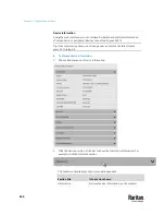
Note: If you have not configured the System SNMP Notification Action to specify
the SNMP destination(s), see
Editing or Deleting a Rule/Action
(on page 429).
Front Panel Settings
You can set up the default mode of the front panel display, and front panel
functions for actuator control, beeper mute or RCM self-test.
Note that available front panel settings are model dependent.
•
Actuator control -- available on all models.
•
Internal beeper's mute function -- available on all PX3TS models.
•
Default front panel mode setup -- available on all models.
•
RCM self-test -- available on those PX3TS models which support residual
current monitoring. See PX3TS Models with Residual Current Monitoring.
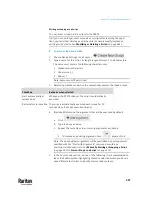
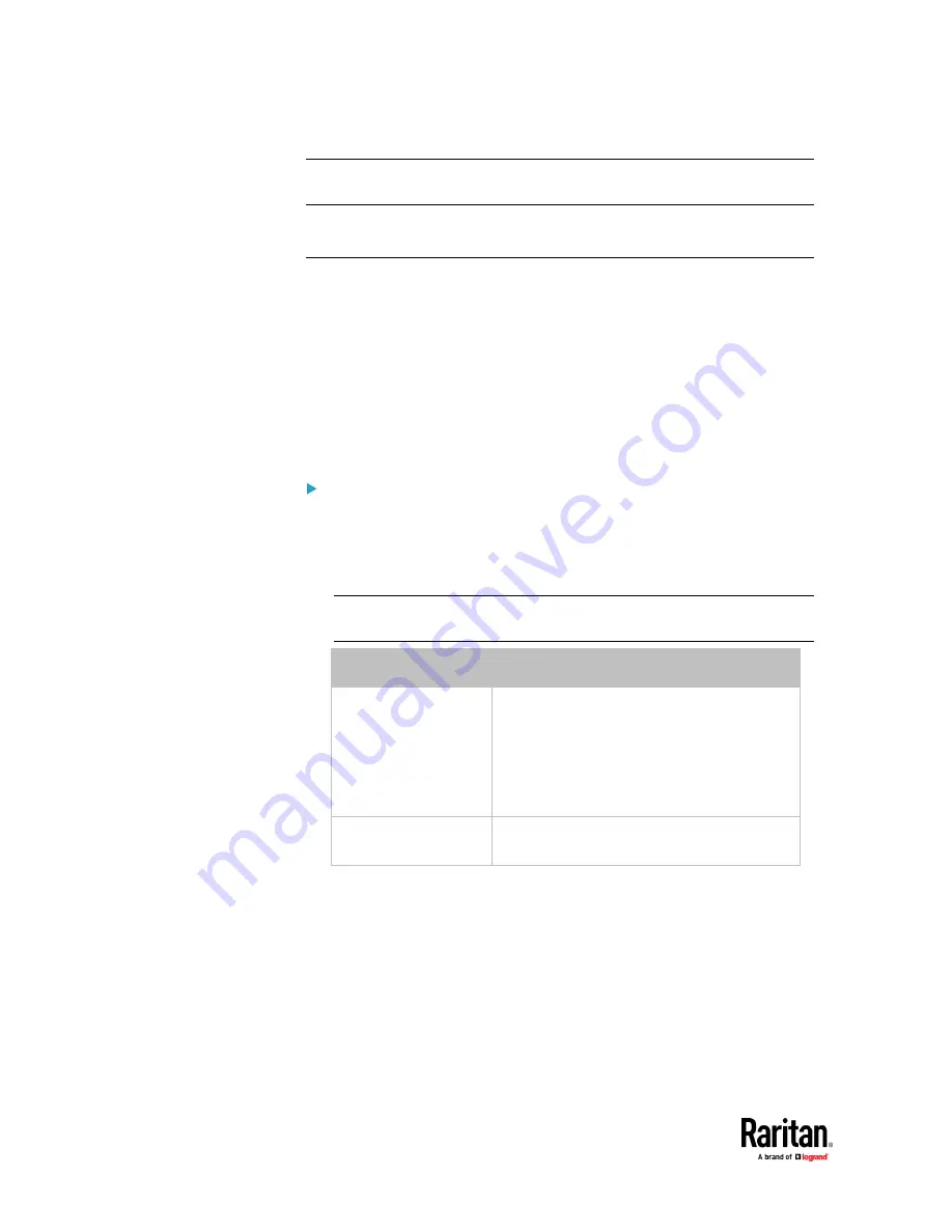
To configure the front panel settings:
1.
Choose Device Settings > Front Panel.
2.
Configure the following:
▪
To configure the default view of the LCD display, select one mode
below.
Note: The default view is shown in the automatic mode. See
Automatic and
Manual Modes
(on page 140).
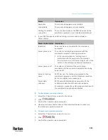
Mode
Data entered
Automatic mode
The LCD display cycles through both the
transfer switch/inlet and overcurrent
protector information. This is the default.
Overcurrent protector information is available
only when your PX3TS has overcurrent
protectors.
Inlet overview
The LCD display cycles through the transfer
switch/inlet information only.
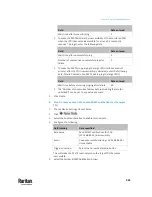
▪
To enable the front panel actuator-control function, select the
'Peripheral actuator control' checkbox.
▪
The built-in beeper's mute control function is enabled per default. To
disable it,
deselect
the 'Mute beeper' checkbox.
▪
By default the front panel RCM self-test function, if available, is
enabled. See Disabling or Enabling Front Panel RCM Self-Test.
3.
Click Save.
If the 'Mute beeper' feature is enabled, you can operate the front panel to
mute it whenever it beeps. See Muting the Internal Beeper.
Содержание Raritan PX3TS
Страница 4: ......
Страница 6: ......
Страница 20: ......
Страница 52: ...Chapter 3 Initial Installation and Configuration 32 Number Device role Master device Slave 1 Slave 2 Slave 3...
Страница 80: ...Chapter 4 Connecting External Equipment Optional 60...
Страница 109: ...Chapter 5 PDU Linking 89...
Страница 117: ...Chapter 5 PDU Linking 97...
Страница 440: ...Chapter 7 Using the Web Interface 420 If wanted you can customize the subject and content of this email in this action...
Страница 441: ...Chapter 7 Using the Web Interface 421...
Страница 464: ...Chapter 7 Using the Web Interface 444...
Страница 465: ...Chapter 7 Using the Web Interface 445 Continued...
Страница 746: ...Appendix A Specifications 726...
Страница 823: ...Appendix I RADIUS Configuration Illustration 803 Note If your PX3TS uses PAP then select PAP...
Страница 824: ...Appendix I RADIUS Configuration Illustration 804 10 Select Standard to the left of the dialog and then click Add...
Страница 825: ...Appendix I RADIUS Configuration Illustration 805 11 Select Filter Id from the list of attributes and click Add...
Страница 828: ...Appendix I RADIUS Configuration Illustration 808 14 The new attribute is added Click OK...
Страница 829: ...Appendix I RADIUS Configuration Illustration 809 15 Click Next to continue...
Страница 860: ...Appendix J Additional PX3TS Information 840...
Страница 890: ...Appendix K Integration 870 3 Click OK...
Страница 900: ......


