


INSTRUCTION / INSTALLATION SHEET
RFLC Event Controller
IS-0531 Rev. D
301Fulling Mill Road, Suite G
Middletown, PA 17057
Phone (800) 321-2343 / Fax (717) 702-2546
www.onqlegrand.com
©Copyright 2012 by Legrand All Rights Reserved.
Page 1 of 4
1. Introduction
The Legrand RFLC Event Controller (see
Figure 1
) provides the capability
of controlling any installed RFLC Lighting Control Product subsystem. This
control capability is user configurable and initiated via Ethernet or WiFi
connected devices, such as PCs and Smart Phones. Using the RFLC Event
Controller, the user can Discover and Locate up to 100 RFLC Zones. Once
RFLC Zones are Discovered, the user can define system lighting control
configurations via: up to 10 Collections of Zones (any discovered Zone can
be included within a Collection), up to 10 lighting Scenes (a maximum of 32
Zones can be included within a Scene), and up to 20 Events (up to 2 Scenes
can be executed per Event). Control of any discrete Zones, Collections, or
Scenes can be initiated via any Ethernet or WiFi connected device (this and
other user-specific functionality for this product is covered in greater detail in
the online Owner’s Manual at
www.legrand.us/support
).
Additionally, automated lighting Scene control of the RFLC Lighting subsystem can be initiated via date and time based Events.
2. Description
•
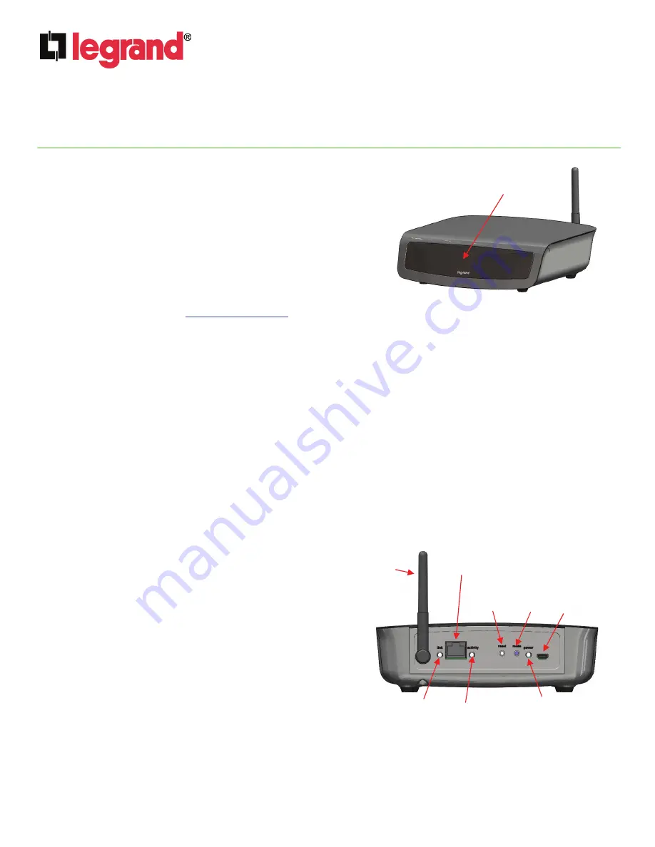
The RFLC Event Controller unit with a front panel 4-line LCD display (see
Figure 1
) is provided and contains the following
rear panel items (see
Figure 2
):
o
Provides one RJ45 jack for Network connection with separate Link and Activity LEDs.
o
Provides one recessed Reset push button switch used to reset the unit to “factory default” condition.
o
Provides one Mode push button switch to select various setup and operational display modes.
o
Provides one Power/Status LED to indicate the unit’s operational states and status.
o
Provides one micro-USB jack for powering the unit.
o
Provides one RF antenna.
•
Also provided is an AC-DC Adapter, (5Vdc output) and Cable Assembly (USB to micro-USB).
3. Installation
IMPORTANT: Read the documentation that is included with all associated Legrand products before
installation. If you are unsure of any of the following installation procedures contact Legrand Technical
Support @ 1-800-321-2343 option 1 or contact a Legrand installer.
NOTE: Prior to this installation, all other RFLC Lighting Products should be installed and configured!
A. Connect a Cat 5 cable from the RJ45 jack on the rear
panel to a Router port that provides DHCP addressing.
B. Connect the AC-DC Adapter to the micro-USB jack on the
rear panel.
C. When the unit is connected to an active LAN with DHCP
enabled Router connection, upon power up the Display
will immediate present “Legrand RFLC Acquiring IP
Address”. After successful IP acquisition, the Display will
list the IP Address as xxx.xxx.xxx.xxx. After a short period
of time the Display will transition to “Legrand RFLC
Current Time mm/dd/yy hh:mm”. The Date and Time will
be correct only if the unit is connected to an active WAN
connection, updating the on-board Real Time Clock. It is
possible to manually set the Date and Time using a PC
Browser to access the device’s Setup Screens.
D. When the RFLC Event Controller is initially powered up, the Power/Status LED will be solid red in color until an IP
Address has been acquired. At the point of IP Address acquisition, the LED will change to an amber color, indicating
a factory status condition
(not configured as part of any RFLC Lighting Subsystem)
. Placing any installed and
configured RFLC Device within a 100’ range into “Learn Mode”, will cause the Power/Status LED to change to
blinking green, indicating that the Event Controller is now house bound to the existing RFLC Lighting Subsystem.
Once the initiating RFLC Device is taken out of “Learn Mode”, the Power/Status LED will change to solid green.
Figure 1
Micro-USB
power
jack
LCD Display
Link LED
Activity LED
Reset
button
Mode
button
Power/Status LED
RJ45 jack
Figure 2
RF
Antenna


