


17/29
Technical data sheet: S000114123EN-1
Updated:
Created: 18/01/2021
Cat. No(s): 0 026 72/73/74/76/78/79
KNX controller multi-application DIN
7 . COMMUNICATION OBJECTS (continued)
7 .8 "Blind" parameter (continued)
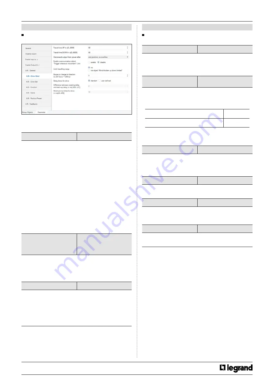
7 .8 .2 "A/B – Drive Blind" parameter
The blind actuator calculates the current position of a blind from the
running time. This calculation has to be performed because the drive
cannot provide any feedback on its position.
Detect travel times (Up/Down)
via detection of end position
*set travel times
This parameter defines the travelling time of the blind. The time
needed for a complete travel from the upper into the lower end
position.
• Set the parameter to “
via detection of end position
”:
The duration of the current flow that the drive uses for the
movement from lower to the upper position. The device is measured
the travel time with current detection. Than up down movements are
stored.
• Set the parameter to “
set travel times
”:
This option is an alternative to automatic travel detection. In this way,
travel times for the lower to the upper end position are measured
with a stop watch then entered into the ETS parameters. The travel
times should be measured as precisely as possible because this times
is determined during ongoing operation.
Travel time UP in s[0…6000]
Travel time DOWN in s[0…6000]
If the “
Detect travel times (Up/Down)
” is selected “
set travel times
”,
this parameters are visible. The measured travel time values are
measured via stopwatch then enter this parameter.
Disconnect output from power after
*end position, no overflow
end po %2 overflow
end po %5 overflow
end po %10 overflow
end po %20 overflow
total travel time + %10 overflow
When the blind has been reached the end position (this means top or
bottom position), the blind is switched off its relay. An overflow time
can be set to ensure the output safely reaches the end position. The
voltage is supplied as an extra time after the blind has been switched
off.
Enable communication object
"Trigger reference movement” 1 bit
enable
*disable
If the parameter is selected “
enable
”, “
Trigger reference movement
”
communication object is visible. The reference movement is triggered
via this communication object. In long time, slight inaccuracies can
occur so the upper and lower end positions are used for unique
determination of current position. A position calibration is possible by
executing the reference movement. A reference travel movement is
not re-triggerable.
7 . COMMUNICATION OBJECTS (continued)
7 .8 "Blind" parameter (continued)
7 .8 .2 "A/B – Drive Blind" parameter (continued)
Position after travel detection
*no reaction, remain in upper end position
move to position before travel detection
If the "
Detect travel times (Up/Down)
” is selected “
set travel times
”,
this parameters are visible. This parameter is configured the blind
position after the reference movement. The step or stop telegram are
ignored while the blind is moving in the reference movement.
Limit travelling range
*no
via object “Blind/shutter up down limited”
via object “Enable limitation”
The blind up and down limit position can be changed by this
parameter.
The limit position only apply for “
Move blind/shutter up-down
”, “
Slat
adjustment/stop up-down
” and automatic communication objects.
Upper limit in % [0…100]
(0% = top; 100% = bottom)
*0
…100
Lower limit in % [0…100]
(0% = top; 100% = bottom)
0…
*100
If the "
Limit travelling range
" parameter is selected "
via object
"Blind/shutter up down limited"
", this parameter is visible. This
parameter set the blind upper/lower limit position in percent.
Pause on change in direction
(1-255 factor * 100ms)
1…
*5
…255
When the blind actuator of a drive that is currently moving, receives a
command to move opposite direction. The blind firstly stops than its
waits for the pause on change in direction than the blind is moved its
new direction.
Delay times for drive
*standard
user defined
If the parameter is selected “
user defined
”, these parameters are
visible. You can show this below.
Different between coasting delay
and start-up delay in ms[-128…127]
-128…
*0
…127
If the blind is closed lower end position, the used blind experiences
dead time between the times when the blind is started the
movement. You can compensate this time with this parameter.
Minimum run time for drive
in ms[0-255]
0…
*50
…255
The blinds have a minimum run time. Please look drive manufacturer
datasheet.
CONTENTS