background image


Page 6/21


Service Manual: PTX8500 UHD


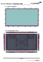
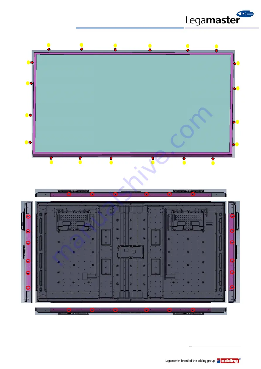
2.1.3. Remove the Bezel 


2.1.4


. Panel BKT (24 


s


crews)


Содержание PTX-8500 UHD

Страница 1: ...Page 1 21 Service Manual PTX8500 UHD Legamaster Service Manual Model No PTX 8500 UHD ...

Страница 2: ...Page 2 21 Service Manual PTX8500 UHD Revision History Version Date Page Section Description V1 0 2015 01 16 All First issued V2 0 2015 04 29 All Change PSU 11012436001 AA ...

Страница 3: ...there for two 2 eye Bolt attachment locations have been placed on top on the unit you can use the eye Bolts provided in the accessory box to hang up this monitor The installation of the hooks as below photo we strongly recommend to follow this method to hang up this monitor Hook 1SM8XXR15Z1 AA ...

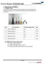
Страница 4: ...erials requiring selective repair can be removed Item Tool Description Tool Size if applicable Qty 1 Electric screwdriver N A 1 pcs 2 Philip Screwdriver N A 1 pcs 3 Philip Screwdriver N A 1 pcs 4 Hexagonal Socket 5mm 1 pcs 5 Mini Plastic Nipper 6 1 pcs 1 2 Operation Space Required 1 2 1 Operation Space Required 1 2 2 Need a clean space 300cm 300cm 1 2 3 Need a stable table surface 200cm 120cm load...

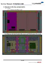
Страница 5: ...Page 5 21 Service Manual PTX8500 UHD 2 Access to the key components 2 1 Panel 2 1 1 Remove the Rear Cover ...

Страница 6: ...Page 6 21 Service Manual PTX8500 UHD 2 1 3 Remove the Bezel 2 1 4 Panel BKT 24 screws ...

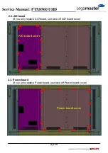
Страница 7: ...ervice Manual PTX8500 UHD 2 2 A D board If you only replace A D board just take off A D board cover 2 3 Power board If you only replace Power board just take off Power board cover A D board cover Power board cover ...

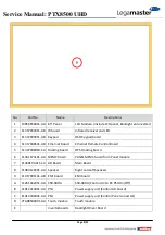
Страница 8: ...Page 8 21 Service Manual PTX8500 UHD 3 Parts descriptions 3 1 Module E ...

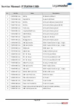
Страница 9: ... 5 11347008963 CA Docking board OPS Docking board 6 11341674101 AA MEMC board PANEL MEMC board from Panel module 7 1134019U011 CA AD Board Main Board 8 11084120391 AA Speaker Right and Left Speakers 9 11017001141 AB EMI board EMI board A 11261362451 AA SSR 40DA SSR 40DA Control AC to DC PSU On Off B 11012413061 AA PSU Power supply unit Control AD board C 11012436001 AA PSU Power supply unit Contro...

Страница 10: ...Page 10 21 Service Manual PTX8500 UHD 3 2 Wiring 3 2 1 Wiring for PCBA ...

Страница 11: ...Page 11 21 Service Manual PTX8500 UHD OPS Dockingboard ...

Страница 12: ...0 extend cable A type A type C 11037003691 AA HDMI cable HDMI cable 1 8m D 11017001241 AA Adaptor wire Adaptor to Docking board E 11060575151 AA FFC Vx1 Pane FFC Vx1 Panel 750mm F 11060540141 AA FFC Vx1 Panel FFC Vx1 Panel 400mm 41 41P G 11060530151 AA FFC Vx1 Panel FFC Vx1 Panel 300mm 51 51P H 11067030591 AA USB2 0 Touch wire Docking to PQ lab touch I 11067030581 AA USB extend cable USB 2 0 exten...

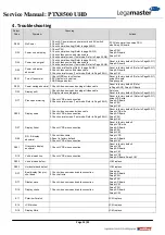
Страница 13: ...video cable 2 Plug the video cable again Auto tune Reset to factory default Refer to Page23 Q1 D17 Press panel waving 1 Check LVDS wire connection 2 Check normal screen Test mode Refer to Page 25 Q3 Reset to factory default Refer to Page23 Q1 swap LVDS wire Swap AD Board Swap PSU Swap LCM D500 Display noise 1 Check video source and video cable 2 Check LVDS wire connection 3 Check normal screen Tes...

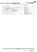
Страница 14: ...ight has failed 1 Check PSU 2 Check Panel Swap PSU Swap LCM T01 No Touch 1 Check USB Cable connection Swap Touch T02 Touch is not accurate 1 Check Screen resolution Touch calibration T03 Not Multi Touch 1 Check Operating Systems 2 Check Touch driver Install Touch driver N500 NDF No defect found N A Function test Burning test 4 hours K01 No 4K2K output 1 Check OSD setting Check OSD Adv Settings EDI...

Страница 15: ...Page 15 21 Service Manual PTX8500 UHD 4 1 Check PSU Functions 4 1 1 11012413061 AA ...

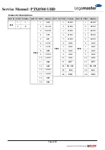
Страница 16: ...L P802 1 DIM P803 1 24VDC P804 1 24VDC 2 N 2 BL ON 2 24VDC 2 24VDC 3 PW ON 3 24VDC 3 24VDC 4 ACD 4 24VDC 4 24VDC 5 DET 5 24VDC 5 24VDC 6 5 2VS 6 GND 6 GND 7 5 2VS 7 GND 7 GND 8 GND 8 GND 8 GND 9 12VDC 9 GND 9 GND 10 12VDC 10 GND 10 GND 11 GND 11 DET 11 DET 12 GND 12 BL ON 12 BL ON 13 12VDC 13 N A 13 N A 14 12VDC 14 DIM 14 DIM 15 GND 16 GND ...

Страница 17: ...he power 5 seconds then go to step a again d If the FUSE is OPEN again then the PSU has been failure 2 Check P802 DC 12V a Turn on the power and check pin13 12V to pin16 GND If measured 12 Volts go to Step 3 b If not then the PSU has been failure 3 Check P803 P804 DC 24V a Turn on the power and check the pin1 24V to pin10 GND of P803 P804 i It must output 24 volts ii If not then the PSU has been f...

Страница 18: ...e 18 21 Service Manual PTX8500 UHD 4 1 2 11012436001 AA Connector Descriptions REF ID PIN SIGNAL REF ID PIN SIGNAL Input 1 FG Output 1 RC 2 AC L 2 RC GND 3 AC R 3 5Vss 4 GND 5 GND 6 24V 7 24V Input Output ...

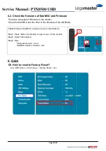
Страница 19: ... is the SubMCU and the other is the firmware of the AD Board Check firmware SubMCU version on menu Information Step1 Press Menu Controller to open menu of the monitor Step2 Select Information Step3 See Firmware Version Vx xx SubMCU Version SubVer Vxx 5 Q A Q1 How to reset to Factory Reset Ans OSD Menu Adv Setup Factory Reset Yes 1 2 3 ...

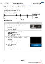
Страница 20: ... Table Status Descriptions Image A Turn on the AC power and click sounds from PSU Abnormal Check AC power source Check PSU functions B Show black screen and Orange LED On Blinks light on and off Abnormal Check OSD setting and firmware Check AD board C Show black screen and see the light from backlight Backlight ON Abnormal Check PSU 12 and 24V functions Check AD board D Show No video input Abnorma...

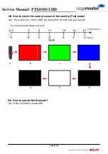
Страница 21: ...w to check the normal screen of the monitor Test mode Ans Press RCU Key Exit or OSD key Menu Exit for more than five seconds The normal screen status as Fig B Q4 How to update the firmware Ans Refer to firmware update SOP U Fig BU B A G C F D E ...

Отзывы: