1
OWNER’S INSTRUCTIONS
Flexzilla
®
20V Cordless Grease Gun Kit
Part No.: L1388LFZ
Legacy Manufacturing Company
Ph: 319.373.7305
INS1388LFZ
Marion, IA 52302 USA
Fx: 319.373.7309
legacymfg.com
(Published 04/10/19)
The color CHARTREUSE as applied to the grease gun and grease hose is a trademark owned by Weems Industries, Inc.
Flexzilla is a registered trademark owned by Weems Industries, Inc. US Pat. No. 8,297,476 CA Pat. No. 2,743,126
1
2
3
4
5
IMPORTANT - Follow each step in sequence to ensure proper loading of grease
1. Apply pressure to barrel pushing
slightly into head.
2. Press LOAD button to release
barrel.
3. Slide barrel out to reload.
4. Press LOAD button and slide
barrel back into head.
5. Release LOAD button.
RAPID RELOAD PROCEDURE
AUTOMATIC BLEEDER VALVE: (see figure 1):
• Bleeds air when reconnectitng the barrel and head.
• Reduces air locks & priming problems.
SHOULDER STRAP (see figure 2):
Attach strap by latching each end into the hole located on the head casting and hanger at the back
of the handle.
HOSE DOCK (see figure 3):
Insert the grease coupler end of the grease hose into the loop hole located on the side of the
housing when gun is not in use.
PRESSURE RELIEF VALVE (see figure 4):
CAUTION: Never allow any part of the human body to come in front of, or in direct contact with a
grease discharge outlet. Direct the air pocket valve away from yourself and other persons in the
vicinity. Never point the nozzle of the gun at yourself or toward anyone else. Pressure relief is factory
preset at 7000 psi +/- 500 psi. If back pressure in the grease line exceeds the preset limit, grease
will then be expelled from this valve to reduce risk of motor overload and limit excessive grease
pressure in grease hose. Do not exceed specifications or alter gun to perform beyond ratings. Such
misuse will void the warranty and can cause possible injury.
WARNING:
Do not adjust or remove pressure relief valve.
2. Shoulder Strap
2
3. Hose Dock
3
1. Automatic Air Bleeder
1
4. Pressure Relief Valve
4
BULK LOADING:
• Remove grease barrel from pump head assembly.
• Insert the open end of the grease barrel into lubricant in bulk container. Slowly pull the
follower handle back while pushing the grease barrel deeper into the lubricant to prevent air
pockets from being pulled into the grease barrel assembly.
• When the follower rod is fully extended, pull it sideways to latch the rod notch into the slot in
the grease barrel end cap.
• Assemble the grease barrel into the pump head. Release the follower rod from slot. Push the
follower rod into the grease barrel.
• Follow priming instructions below.
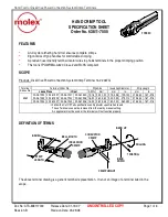
FILLER PUMP LOADING (Using Optional Filler Nipple: Part #L2461 - Not Included):
• Replace the plug in the head of the grease gun with a 1/8” MNPT filler nipple for loading with
a manually-operated grease transfer pump. Follow filler pump instructions also.
• Insert the gun filler nipple into the filler pump socket.
• Operate the filler pump to fill the grease barrel. When the follower rod can be pulled out
without effort and the rod notch is exposed, the grease barrel is filled. The follower rod will be
extended approximately 8” (20.3 cm)
• Push the follower rod into the grease barrel assembly.
• Follow priming instructions below.
ASSEMBLY