background image

ZMMM

3TIVEXMRKZSPXEKISJTPSXXIV

%P]WQEMRXIRERGIQERYEP

%%

3TIVEXMRKZSPXEKISJTPSXXIV

!

%HIRUHVZLWFKLQJRQWKHSORWWHUFKHFNWKDWLWVRSHUDWLQJYROWDJHLV

FRUUHFW7KHSORWWHULVVXSSOLHGFRQILJXUHGIRUDPDLQVYROWDJHRI

9

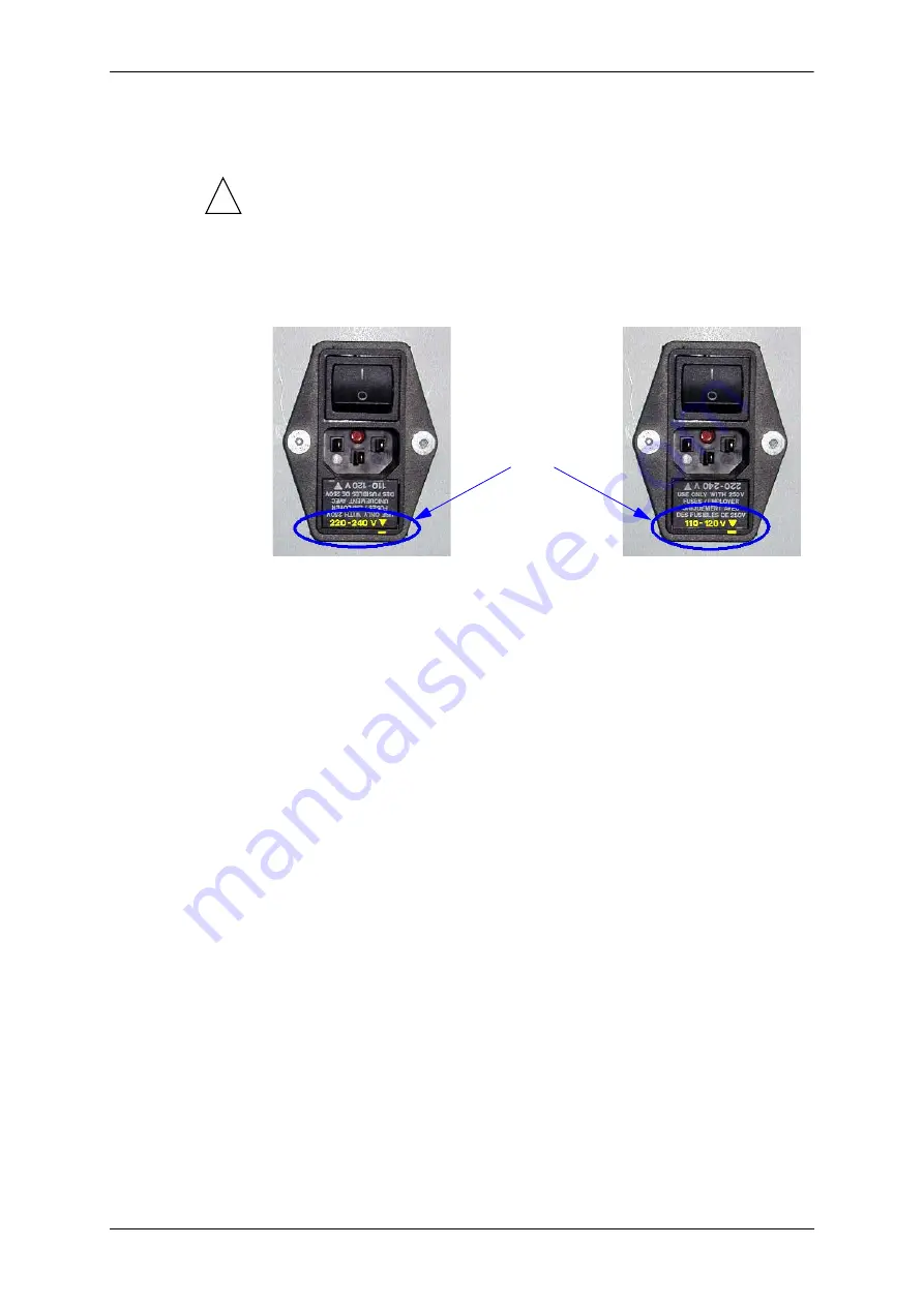
To change the plotter’s serviceable voltage, simply invert the protective fuse 
cartridge, which is located underneath the entry point of the mains cord. 

 1EMRWGSVH

 )YVSTIERGSYRXVMIW

The mains cord supplied with Alys plotters conforms with European safety 
standards.

 97%ERH'EREHE

Le cordon d’alimentation du traceur Alys doit être du type :

3-core type SJT, rated 18 AWG minimum for 10A, 250V.

The plotter's 

operating voltage 

corresponds to the 

voltage indicated by 

the arrow next to the 

locating mark on the 

fuse cartridge.

220 - 240v

110-120V

Содержание Alys 120

Страница 1: ...1EMRXIRERGI QERYEP Z I de Marticot BP 34 33611 CESTAS Cedex France 33 0 5 57 97 80 00 Fax 33 0 5 57 97 82 32 543016AA Edition 1 March 2001 0IGXVE ...

Страница 2: ...s in order to improve their reliability or functioning Its publication does not imply that the material that appears here is exempt from industrial ownership rights and does not confer any license to these rights In addition Lectra Systèmes does not take responsibility for repercussions of any nature arising from the use of this information 6IKMWXIVIH XVEHIQEVOW Alys is a registered trademark of L...

Страница 3: ... the country The QWURGXFWLRQ chapter describes the plotter and its control panel The minimum configuration required for the operating PC is indicated in this chapter A data sheet summarizes its technical specifications The 3ORWWHU WHVWV chapter provides access to the advanced maintenance software for carrying out specific adjustments and self tests on the plotter The 0HFKDQLFDO PDLQWHQDQFH chapter...

Страница 4: ...MZ P W QEMRXIRERGI QERYEP ...

Страница 5: ... 1MRMQYQ VIUYMVIH GSRJMKYVEXMSR EVH EVI GSRJMKYVEXMSR 7SJX EVI GSRJMKYVEXMSR EXE 7LIIX 4PSXXIV 8IWXW GGIWW XS XLI EHZERGIH QEMRXIRERGI WSJX EVI 9THEXMRK TPSXXIV IPIGXVSRMGW QEREKIQIRX TVSKVEQ 7 RGLVSRM MRK TPSXXIV GPSGO MXL XLI 4 GPSGO 4PSXXIV XIWXW SRJMKYVEXMSR EWMG XIWXW 1IGLERMGEP QEMRXIRERGI 8SSPW RIGIWWEV JSV QEMRXIRERGI IRIVEP VIGSQQIRHEXMSR 4VIWIRXEXMSR SJ WYF EWWIQFPMIW VSRX ZMI SJ TPSXXIV...

Страница 6: ...GSZIV 6IQSZEP SJ PEXIVEP GSZIVW 0IJX WMHI SJ 4PSXXIV WIIR JVSQ XLI FEGO 6ITPEGIQIRX SJ XLI JMPP TYQT XYFI 6ITPEGIQIRX SJ XLI QEMR IPIGXVSRMGW FSEVH 6ITPEGMRK XLI QEMR XVERWJSVQIV 1SYRXMRK 6IQSZMRK XLI QSXSV 6ITPEGMRK XLI TETIV JIIH IRGSHIV 6ITPEGMRK XLI TETIV IRGSHIV XIRWMSR FEV 6MKLX WMHI SJ 4PSXXIV WIIR JVSQ XLI FEGO LERKMRK WIEPW 6IQSZEP QSYRXMRK SJ GEVFSR WPMHMRK GSRXEGXW 6IQSZEP SJ GEVVMEKI Y...

Страница 7: ...LV ODEHO LQGLFDWHV WKH SUHVHQFH RI VDIHW LQVWUXFWLRQV It is imperative that the safety instructions given in this manual be observed to avoid the risk of accidents PIGXVMGEP WEJIX YWIW KHQ UHSODFLQJ D IXVH UHSODFH LW ZLWK RQH RI WKH VDPH W SH DQG WKH VDPH UDWHG VSHFLILFDWLRQV LQ RUGHU WR SUHVHUYH WKH SURWHFWLRQ DIIRUGHG DJDLQVW WKH GDQJHU RI ILUH 2EVHUYH WKH PRXQWLQJ GLUHFWLRQ RI WKH IXVH W GHWHUP...

Страница 8: ...ert the protective fuse cartridge which is located underneath the entry point of the mains cord 1EMRW GSVH YVSTIER GSYRXVMIW The mains cord supplied with Alys plotters conforms with European safety standards 97 ERH EREHE Le cordon d alimentation du traceur Alys doit être du type 3 core type SJT rated 18 AWG minimum for 10A 250V The plotter s operating voltage corresponds to the voltage indicated b...

Страница 9: ...ink cartridges 7XSVEKI Keep the container in a dry place at room temperature Take precautionary measures against electrostatic discharge Keep away from powerful oxidizing agents 6IG GPMRK YWIH MRO VIWIVZSMVW Disposal must conform with national and local regulations Chemical residues are generally considered as special residue 4ETIV 7XSVEKI Recommended storage conditions for paper are as follows Te...

Страница 10: ... ERHPMRK ERH WXSVEKI SJ GSRWYQEFPI MXIQW P W QEMRXIRERGI QERYEP ...

Страница 11: ...GI QERYEP RXVSHYGXMSR 4VIWIRXEXMSR SJ XLI P W MRONIX TPSXXIV 6SPP SJ TETIV WYTTPMIH RHYWXVMEP GEWXIVW 4VSXIGXMSR GSZIVW SRXVSP OI FSEVH TPSXXIV QEMRW GSRRIGXMSR VIEV JEGI 6IGITXEGPI JSV GSRWYQEFPI MXIQ HYVMRK YWI 6IGITXEGPI JSV WXSVEKI SJ GSRWYQEFPI MXIQ ...

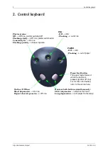
Страница 12: ...iving data 1 2II OK ODVKLQJ out of ink 3 3 5 2II OK ODVKLQJ out of paper 3DSHU IHHG EXWWRQ The paper feeds forward while the button is pressed plotter off line For further information refer to the online help 2Q OLQH 2II OLQH 6KRUW GHSUHVVLRQ On line 5HSHDW VKRUW GHSUHVVLRQ Off line HSUHVV ERWK EXWWRQV VLPXOWDQHRXVO 6KRUW GHSUHVVLRQ empties the head RQJ GHSUHVVLRQ cuts paper transversely ...

Страница 13: ...28 Mb of memory 1 parallel port to connect to the plotter or 1 USB port Windows 2000 only or 1 RS232 serial port RX PXVW UHVSHFW WKH UHFRPPHQGHG FDEOH OHQJWKV WR FRQQHFW WKH SORWWHU WR LWV RSHUDWLQJ 3 HFWUD 6 WÅPHV FDQQRW JXDUDQWHH FRUUHFW O V SORWWHU IXQFWLRQLQJ LI D FRQQHFWLRQ FDEOH ORQJHU WKDQ WKDW LQGLFDWHG EHORZ LV XVHG HQWURQLFV SDUDOOHO PHWHUV PD LPXP 86 QR UHSHDWHU PHWHUV PD LPXP 56 VHULDO...

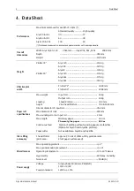
Страница 14: ...ut roll 40Kg Output roll 40Kg Loading 1 head Plotter 744 mm height 2 4 head Plotters 744 1024 mm Interior diameter of input roll 76 2 mm Max diameter of rolls 200 mm Max winding error on input roll 2 mm Max length Ordinary paper 400 m 7KHUPDO JOXH SDSHU P Continuous feed Option of plotting without winding paper onto feed bar Option for Alys30 and Alys30L plotters Paper cutter Not available on Alys...

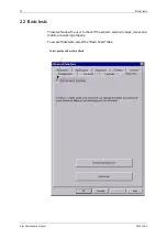
Страница 15: ...IWXW GGIWW XS XLI EHZERGIH QEMRXIRERGI WSJX EVI To access the advanced maintenance tools The main screen of routine maintenance is displayed 1SZI XLI QSYWI GYVWSV SRXS XLI P W MGSR 6MKLX GPMGO MXL XLI QSYWI R XLI QIRY LMGL ETTIEVW WIPIGX l HZERGIH 1EMRXIRERGIz 4VIWW XLI FYXXSR ...

Страница 16: ...lotter electronics management update update of electronics management in an attempt to improve or correct bugs EMP WEJI QSHI I WKH WKUHH V RQ WKH FRPPDQG NH ERDUG UHPDLQ 21 WKH SORWWHU HOHFWURQLFV PDQDJHPHQW SURJUDP ZLOO QHHG WR EH UHORDGHG Q WKLV FDVH WKH k DLO VDIH PRGHy LV VHOHFWHG E GHIDXOW ZKHQ O V SHUW VWDUWV Access to tools to test the plotter will be available only after the plotter electr...

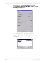
Страница 17: ... WKDW RSHQV WKH IDLO VDIH PRGH LV FKHFNHG 1HYHU XQFKHFN WKLV PRGH ZKHQ XSGDWLQJ WKH SORWWHU SURJUDP DV VHULRXV PDOIXQFWLRQV PD RFFXU Click the Update button to load the program in the plotter In the window that opens click on the O V3URJUDP file to load and then on the Open button ...

Страница 18: ... problem arises during the update an alert window will appear on screen 7 RGLVSRM MRK TPSXXIV GPSGO MXL XLI 4 GPSGO To work properly the plotter has an internal clock that must be synchronized with the controlling PC clock To do this click on set clock and the time of PC clock is sent to the plotter GXMSRW EPVIEH XEOIR GXMSRW MR TVSKVIWW 7XEXYW SJ EGXMSR MR TVSKVIWW ...

Страница 19: ...ling electronics are working properly the following screen appears 7KH QXPEHU RI KHDGV DUH DXWRPDWLFDOO VHW WR IRU O V DQG O V RU O V O V O V O V SORWWHUV WKH QXPEHU RI KHDGV LV VHW WR E GHIDXOW 7KH QXPEHU PXVW EH VHW WR IRU O V DQG O V P W P W 0 GLIGO XLI FS VIUYMVIH P W P W 0 4YX VIUYMVIH ...

Страница 20: ...W QEMRXIRERGI QERYEP EWMG XIWXW These tests allow the user to check if the sensors solenoid valves relays and motors are working properly To access these tests select the Basic Tests tabs 8S XIWX TYQTW ERH QSXSVW GLIGO ...

Страница 21: ...ps and purge pumps of the ink circuit only if Activate commands reserved for experts was checked in the previous Advanced functions window RU VRPH WHVWV WKH SURWHFWLYH FRYHU XVHG IRU WKH SULQW KHDGV ZLOO QHHG WR EH UHPRYHG Follow the instructions given in the chapter 0HFKDQLFDO PDLQWHQDQFH LVPDQWOLQJ WKH SULQWLQJ KHDG 5HPRYLQJ WKH SURWHFWLYH KHDG FRYHU Sensor LEDs activated O V O V Ink reservoir 1...

Страница 22: ... command keyboard When the head is almost at the end the head board LED should change status The LED displayed in the control window on screen should also change status 0MRIEV IRGSHIV 1 Carefully move the head by hand The LED on the head board should flash while the head is moving SZIV GPSWIH 1 When the cover is closed the LED displayed on the control screen should be on Opening the cover only 4 c...

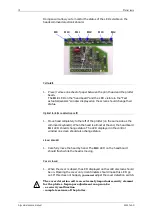
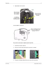
Страница 23: ...ir 2 Move your hand in the area where the reservoir is located 3 The sensor should go off each time you move your hand across 7GVI XS PSGO GSZIV W MXGL TSWMXMSR EJXIV EHNYWXQIRX 7PMHI XLI HIXIGXMSR W MXGL XS EHNYWX MXW XLVS XLVIWLSPH 7II JSPPS MRK HVE MRK XS HIXIVQMRI XLI HIXIGXMSR TSMRX 8LI GSZIV HIXIGXMSR W MXGL QYWX EGXMZEXI JSV E QE MQYQ GSZIV STIRMRK SJ GQ z ...

Страница 24: ...O V O V O V WKH FRPPDQGV FRUUHVSRQGLQJ WR WKHVH QRQ H LVWHQW VROHQRLG YDOYHV DUH JUD HG RXW IRXMRK 1 Same test procedure as for the other solenoid valves see above MPP TYQT 7KLV WHVW ZLOO FKHFN WKH URWDWLRQ GLUHFWLRQ RI WKH SXPS PRWRU I WKH SXPS PRWRU LV WXUQLQJ LQ WKH ZURQJ GLUHFWLRQ WKH LQN FLUFXLW FDQQRW EH VXSSOLHG 7KLV WHVW PXVW QRW EH GRQH XQOHVV WKH SXPS LV EHLQJ UHSODFHG 7KH WXEH VKRXOG QR...

Страница 25: ...H GRQH XQOHVV WKH SXPS LV EHLQJ UHSODFHG 7KH WXEH VKRXOG QRW EH SODFHG LQ WKH SXPS WR GR WKH WHVW 1 Make sure the tube is not placed inside the pump to be tested 2 Click the Purge button The LED opposite the button should light up and the pump should be working 3 Follow the same procedure as for the fill pump test 4 When the test has finished click the Purge button again The LED opposite the butto...

Страница 26: ... button 2 To validate this command click the Apply button The head moves along the beam Positive travel direction towards purge station Negative travel direction towards control keyboard 3 Make sure the value displayed in the Status Y encoder varies as the head moves 4 Make sure the direction of the value shown corresponds to the travel direction see point 2 LVM XWWRQ LI WKLV EXWWRQ OLJKWV XS GLVM...

Страница 27: ...r feed should make the value in the control window decrease LVM 3 XWWRQ LI WKLV EXWWRQ OLJKWV XS GLVMXQFWLRQ H LVWV LQ WKH 3 PRWRU FRPPDQG OLFN WKH 067 EXWWRQ WR UHDUP WKH EUHDNHU OLFN WKH 067 EXWWRQ DJDLQ WR UHVWDUW WKH WHVW 5HVHWWLQJ WKH HQFRGHU GLVSOD ZLQGRZ FOLFN WKH EXWWRQ 4ETIV YR MRHMRK E IW 1 Select the motor to test by clicking on the corresponding radio button 2 Click the MST button 3 To...

Страница 28: ...ke sure the value in the Encoder bar window is zero If this is not the case click the 0000 button 6 Turn the bar towards the plotter beam at the front of the plotter The value in the control window should increase value shown should be positive R QRW WXUQ WKH EDU PRUH WKDQ KDOIZD GXULQJ WKLV WHVW 7 Turn the bar towards the rear of the plotter The value in the control window should decrease value s...

Страница 29: ...river Brake fluid ref Loctite 222 Microlube grease Klubert 118010 A container for keeping dismantled parts Adhesive tape A dynamometric spanner A spring scale IRIVEP VIGSQQIRHEXMSR OZD V VWDUW E XQSOXJJLQJ DOO WKH HOHFWULFDO FRQQHFWLRQV OLQNLQJ WKH SORWWHU WR WKH PDLQV DQG WR WKH FRQWUROOLQJ 3 Apply brake fluid to all tightening parts on re assembly To ensure maintenance under the best conditions ...

Страница 30: ...SRX ZMI SJ TPSXXIV Q RUGHU WR GHILQH WKH OHIW DQG ULJKW VLGHV RI WKH SORWWHU ORRN IURP EHKLQG WKH SORWWHU DQG FRQVLGHU WKH GLUHFWLRQ RI IORZ RI WKH SDSHU The following rules result 7MRKPI LIEH TVMRXMRK FPSGO Cover open 6MKLX WMHI SJ TPSXXIV 0IJX WMHI SJ TPSXXIV VSRX MVIGXMSR SJ TETIV JPS ...

Страница 31: ...4VIWIRXEXMSR SJ WYF EWWIQFPMIW P W QEMRXIRERGI QERYEP 0IJX WMHI SJ 4PSXXIV WIIR JVSQ XLI FEGO 6MKLX WMHI SJ 4PSXXIV WIIR JVSQ XLI FEGO EGO MVIGXMSR JPS TETIV EGO ...

Страница 32: ...QSZEP SJ LIEH TVSXIGXMSR GSZIV To remove the cover protecting the heads do the following facing the head grasp the sides of the cover move them apart slightly and pull the cover upwards 6MFFSR RO PIZIP WIRWSV PIGXVSRMGW FSEVH YJJIV VIWIVZSMV SRRIGXMSR GEFPI JSV XLI VIWIVZSMV PIZIP WIRWSV RO MRPIX ...

Страница 33: ...P WIRWSV Each buffer reservoir has its own sensor to detect ink level 0MJX SJJ XLI WIRWSV MXL E GYXXIV 9RTPYK XLI MRO PIZIP WIRWSV GEFPI JVSQ XLI IPIGXVSRMGW FSEVH 6IQSZI XLI HIJIGXMZI WIRWSV 6IQSZI XLI TVSXIGXMSR GSZIVMRK XLI WIRWSV EHLIWMZI VMRK XLI WIRWSV XS XLI IRH EKEMRWX XLI TSWMXMSRMRK FPSGOW EW WLS R MR XLI TLSXS FIPS LIR XLI WIRWSV MW MR TPEGI TVIWW SR MX JMVQP XS TEWXI MX XS XLI VIWIVZSM...

Страница 34: ...KH UHVHUYRLU PDNH VXUH WKDW WKH VXUIDFH RI WKH UHVHUYRLU LV FOHDQ GU DQG IUHH RI JUHDVH Re plug the ink level sensor cable into the electronics board When doing this make sure the connector is plugged in the right way and connect the cable to the appropriate connector in the case of a multi head ...

Страница 35: ...be on the reservoir HHS WKH VHDO 0DNH VXUH QRW WR ORVH LW H FDUHIXO QRW WR VSLOO LQN RQ WKH PDFKLQH RU RQ RXU FORWKHV 3URWHFW WKH HQGV ZLWK DGKHVLYH WDSH 3 Remove the ink delivery tube from its housing 4 Unscrew the buffer reservoir fastening screws situated outside the plotting block casing 7II l6IQSZEP SJ XLI LIEH FYJJIV VIWIVZSMV YRMXz XS VIQSZI XLI VIWIVZSMV FYJJIV EWWIQFP IUYMTTIH MXL XLI HMW...

Страница 36: ...reservoir assembly on the plotting block casing and tighten the fastening screws on the outside 0 2 N m 2 Remove the ink delivery pipe housing protection if necessary 3 Install the seal and reposition the ink delivery pipe into its housing 4 Screw the ink delivery tube lock nut to the reservoir Tighten to one quarter turn 5 Plug the ink level sensor cable to the electronics board if necessary ...

Страница 37: ...g the buffer reservoir HHS WKH VFUHZV DQG ZDVKHUV IRU UH DVVHPEO 9RTPYK XLI XLVII VMFFSR GEFPIW 9RTPYK XLI MRO PIZIP WIRWSV GEFPI 9RTPYK XLI VMFFSR GEFPI JVSQ PMRIEV IRGSHIV 9RTPYK XLI GEFPI JVSQ XLI TETIV HIXIGXMSR WIRWSV 9RWGVI XLI JEWXIRMRK WGVI W JVSQ XLI FSEVH SR XLI TVMRXMRK LIEH WGVI W JSV P W WGVI W JSV P W WGVI W JSV P W SY GER EGGIWW XLI PS IV WGVI W F VIQSZMRK XLI FYJJIV VIWIVZSMV ...

Страница 38: ... the electronics board Proceed with the Dismantling the buffer reservoir described above then 8S VIQSZI XLI FSEVH LSPH MX ERH TYPP XLI JSYV GSVRIVW XS EVHW SY WMQYPXERISYWP I GEVIJYP RSX XS HEQEKI XLI GSRRIGXSV FILMRH XLI FSEVH 9RWGVI XLI PSGO RYXW JVSQ XLI LIEH LSPHMRK FEVW 6IQSZI XLI LSPHMRK FEVW EVIJYPP VIQSZI XLI LIEH I GEVIJYP RSX XS XSYGL ER XLMRK MXL XLI WYVJEGI SJ XLI TVMRX LIEH 8LMW WYVJE...

Страница 39: ...ccess to the fastening screws of the block and so have carried out the Removal of head protection cover 6IQSZI XLI LIEH FYJJIV VIWIVZSMV EWWIQFP EJXIV TVSGIIHMRK MXL XLI l6IQSZEP SJ XLI TPSXXMRK FPSGOz IEH FYJJIV VIWIVZSMV EWWIQFP VIQSZIH 9RWGVI XLI JSYV JEWXIRMRK WGVI W SJ XLI FPSGO WIIR JVSQ MWGSRRIGX XLI VMFFSR GEFPI JVSQ XLI PMRIEV IRGSHIV XS JVII XLI TPSXXMRK FPSGO ...

Страница 40: ...oved to reach the fastening screws of the anti static brushes 6ITPEGIQIRX Reposition the anti static brushes on the plotting block support and screw in the four fastening screws lightly 6ITPEGIQIRX SJ XLI TPSXXMRK FPSGO Position the plotting block with care for the guide studs 9RWGVI XLI X S JEWXIRMRK WGVI W SJ IEGL ERXM WXEXMG FVYWL ERH VIQSZI XLIQ ...

Страница 41: ...IQIRX SJ XLI LIEH FYJJIV VIWIVZSMV YRMX The Removal of the electronics board must be carried out Pass the head under the plotting block with caution raise it as shown below 4PEGI XLI PMRIEV IRGSHIV VMFFSR GEFPI FIX IIR XLI FSEVH ERH XLI TPSXXMRK FPSGO GEWMRK 4VMRXMRK LIEH 8LI LIEH QSYRXMRK HMVIGXMSR GER FI HIXIVQMRIH F X S GIRXIVMRK FPSGOW RO WYTTP XYFI LIR QSYRXMRK FI GEVIJYP RSX XS XSYGL XLI WYV...

Страница 42: ...XLI LIEH MW GSVVIGXP WYTTSVXIH SR XLI TPSXXMRK FPSGO 6ITPEGMRK XLI IPIGXVSRMGW FSEVH I GEVIJYP XS GSVVIGXP EPMKR XLI IPIGXVSRMGW FSEVH GSRRIGXSV MXL XLI TVMRXMRK LIEH GSRRIGXSV LIR QSYRXMRK QMWEPMKRQIRX GER HIWXVS FSXL GSRRIGXSVW TTP WSQI FVEOI JPYMH SR XLI JEWXIRMRK WGVI W 6ITPEGI XLI EWLIVW ERH WGVI XLI FSEVH JEWXIRMRK WGVI W SRXS XLI TVMRXMRK LIEH XSVUYI SJ 2 Q WGVI W JSV P W WGVI W JSV P W WGV...

Страница 43: ...cable direction protected side of plug in blue visible from above 2 Insertion and guide 3 Connection check 4 Check that the ink level sensor cable is correctly connected to the electronic board 6IGSRRIGX XLI PMRIEV IRGSHIV VMFFSR GEFPI I GEVIJYP SJ XLI GEFPI HMVIGXMSR TVSXIGXIH WMHI SJ TPYK MR FPYI ZMWMFPI JVSQ EFSZI 6IGSRRIGX XLI TETIV HIXIGXMSR WIRWSV GEFPI 4 I GEVIJYP SJ XLI GEFPI HMVIGXMSR TVS...

Страница 44: ...RX SJ XLI LIEH TVSXIGXMSR GSZIV Three safety blocks hold the cover in place When replacing the cover slightly move the corners of the cover apart and position it so that the holding blocks are fully inserted into the cover 4SWMXMSR SJ XLI WEJIX FPSGOW JSV XLI LIEH GSZIV ...

Страница 45: ...UDWLYH WR XQSOXJ WKH ULEERQ FDEOH OLQNHG WR WKH FRPPDQG NH ERDUG EHIRUH FRPSOHWHO UHPRYLQJ WKH SURWHFWLYH FRYHU To unplug the ribbon cable from the keyboard do the following 4SWMXMSR SJ GSZIV JEWXIRMRK WGVI W 6MFFSR GEFPI PSGOIH 6MFFSR GEFPI YRPSGOIH 6MFFSR GEFPI 4YPP SR XLI VMFFSR GEFPI XS VIQSZI MX JVSQ XLI MVQP TYWL SR XLI lIEVWz PSGEXIH SR XLI WMHIW SJ XLI GSRRIGXSV XS YRPSGO XLI VMFFSR GEFPI ...

Страница 46: ...SJ 4PSXXIV WIIR JVSQ XLI FEGO Removed left side protection cover of the plotter OZD V VWDUW E XQSOXJJLQJ DOO WKH HOHFWULFDO FRQQHFWLRQV OLQNLQJ WKH SORWWHU WR WKH PDLQV DQG WR WKH FRQWUROOLQJ 3 QSXSV MPP TYQT 4ETIV JIIH IRGSHIV 9T EVH TETIV HVMZI QSXSV 1EMR IPIGXVSRMGW FSEVH ...

Страница 47: ... plotter Put clamps on the pump s entry tube and exit tube Make sure the tubes are securely closed off 3TIR XLI TYQT GSZIV PEQTW QSYRXIH SR XLI TYQT HIPMZIV ERH SYXTYX XYFIW 2SXI XLI TSWMXMSR SJ GEQW XS JEGMPMXEXI I XVEGXMSR SJ XLI XYFI 4VIWW XLI WQEPP TEVXW QEHI SJ LMXI TPEWXMG XS VIQSZI XLI XYFI JVSQ XLI TYQT 8LI XYFI MW SYX SJ XLI TYQT ...

Страница 48: ...y pushed into the adapters Remove the pump entry tube clamps Make sure the new tube is correctly installed in the body of the pump Mounting is completed 4SWMXMSR XLI XYFI MR MXW LSYWMRK F KYMHMRK MX MXL SYV JMRKIV 4SWMXMSR XLI GEQW XS IREFPI XLI XYFI XS FI MRWXEPPIH SRRIGX XLI XYFI MRXS XLI LMXI TPEWXMG TEVX XS WIX MXW JMREP TSWMXMSR 8YVR XLI FSH SJ XLI TYQT ERXM GPSGO MWI F LERH SV G GPIW XS TSWM...

Страница 49: ...SOXJJLQJ DOO WKH HOHFWULFDO FRQQHFWLRQV OLQNLQJ WKH SORWWHU WR WKH PDLQV DQG WR WKH FRQWUROOLQJ 3 Removed left side protection cover of the plotter keyboard side 1 Remove the electronics shielding cover 2 Unplug all the board connectors identified with arrows SZIV JEWXIRMRK WGVI 3TIR XLI GSZIV E JI GIRXMQIXIVW XLIR VIQSZI ...

Страница 50: ...the connectors are plugged to the appropriate places 6 Put the electronics shielding cover back into place 7 Replace the side protective cover fasten it and plug the command keyboard back in 6ITPEGMRK XLI QEMR XVERWJSVQIV OZD V VWDUW E XQSOXJJLQJ DOO WKH HOHFWULFDO FRQQHFWLRQV OLQNLQJ WKH SORWWHU WR WKH PDLQV DQG WR WKH FRQWUROOLQJ 3 Left side protection cover of the plotter removed 1 Remove the e...

Страница 51: ...sure all the connections are correct 6 Put the transformer base plate back into place and screw in the fastening screws 7 Put the main electronics board back in place see the Replacement of the main electronics board 1SZI XLI XVERWJSVQIV WYTTSVX TPEXI ERH VIQSZI MX F TYPPMRK YT 9RWGVI XLI JEWXIRMRK WGVI VITPEGI XLI XVERWJSVQIV ERH VIQSYRX MX 9RTPYK XLI XVERWJSVQIV LIR VITPEGMRK XLI XVERWJSVQIV FI ...

Страница 52: ...tening screws situated beneath the motor Loosen the drive belt by sliding the motor assembly Unscrew the earth braid on the opposite side to the motor Unplug connector J from the electronics board and remove the motor assembly Keep the fastening screws and the motor attachment strap Reinstall a new motor Replace the attachment strap and reposition the screws Replace the drive belt and tighten it t...

Страница 53: ...inal if necessary Reposition a new carbon in the housing and re screw the nut with care Reconnect the terminated wires if necessary 6ITPEGMRK XLI TETIV JIIH IRGSHIV OZD V VWDUW E XQSOXJJLQJ DOO WKH HOHFWULFDO FRQQHFWLRQV OLQNLQJ WKH SORWWHU WR WKH PDLQV DQG WR WKH FRQWUROOLQJ 3 Left side protection cover of the plotter removed 9RWGVI XLI RYX ERH TYPP SR XLI XIVQMREP XS VIQSZI XLI GEVFSR 4ETIV JIIH...

Страница 54: ...ed encoder connection cable back into place and plug it back onto the main electronics board MWGSRRIGX XLI TETIV JIIH IRGSHIV GEFPI JVSQ XLI QEMR IPIGXVSRMGW FSEVH EWXIRMRK WGVI JSV XLI TETIV JIIH IRGSHIV YRMX 6IEV ZMI SJ XLI FIEQ 9RWGVI XLI JEWXIRMRK WGVI W JVSQ XLI IRGSHIV YRMX ERH VIQSZI MX JVSQ XLI FIEQ 4YX XLI TETIV JIIH IRGSHIV YRMX MRXS TPEGI F WPMHMRK MX XS XLI MRWMHI SJ XLI FIEQ ...

Страница 55: ... N m 6ITPEGMRK XLI TETIV IRGSHIV XIRWMSR FEV OZD V VWDUW E XQSOXJJLQJ DOO WKH HOHFWULFDO FRQQHFWLRQV OLQNLQJ WKH SORWWHU WR WKH PDLQV DQG WR WKH FRQWUROOLQJ 3 Left side protection cover of the plotter removed 1 Remove the command electronics shielding cover 2 Unplug the ribbon cable of the encoder to be replaced from the main electronics board 0 5 to 0 7 mm 4ETIV XIRWMSR FEV IRGSHIVW JSV YTTIV ERH...

Страница 56: ... the encoder 6 Replace the encoder with a new one MWGSRRIGXMSR SJ XLI TETIV XIRWMSR FEV IRGSHIV GEFPI JVSQ XLI YTTIV VSPPIV MWGSRRIGXMSR SJ XLI IRGSHIV GEFPI JVSQ XLI TETIV XIRWMSR FEV JVSQ XLI PS IV VSPPIV 9RWGVI XLI JEWXIRMRK WGVI W JVSQ XLI TVSXIGXMZI GSZIV 6IQSZI XLI TVSXIGXMZI GSZIV JVSQ XLI TETIV XIRWMSR IRGSHIV HVMZI TMRMSR 9RWGVI XLI JEWXIRMRK WGVI W JVSQ XLI TMRMSR SR XLI IRGSHIV W E MW 9...

Страница 57: ...he fastening screws 8 Put the protective cover back into place 9 Reconnect the encoder to the main electronics board Observe the connection direction of the connector guided connector 10 Put the electronics shielding cover back into place 11 Replace the side protective cover fasten it and plug the command keyboard back in ...

Страница 58: ...4PSXXIV WIIR JVSQ XLI FEGO P W QEMRXIRERGI QERYEP 6MKLX WMHI SJ 4PSXXIV WIIR JVSQ XLI FEGO Right side protection cover of the plotter removed 4SWMXMSRMRK SJ WIEPW TIV LIEH EVFSR WPMHMRK GSRXEGXW PSGEXIH FIPS GEVVMEKI ...

Страница 59: ...G FUHDWH VHDOLQJ GHIHFWV ZKHQ WKH KHDGV DUH SXUJHG 6IQSZEP QSYRXMRK SJ GEVFSR WPMHMRK GSRXEGXW Loosen the fastening screw and remove the carbon sliding contacts Change the carbon sliding contacts and reposition it so that it rubs correctly on the balancing arm Tighten the screw lightly 9RWGVI XLI JEWXIRMRK WGVI W JVSQ XLI WIEP 6IQSZI XLI WIEP ERH MXW QIXEP LSPHMRK TPEXI RWXEPP E RI WIEP ERH MXW LS...

Страница 60: ...de sockets To do this carry out the Removal of the plotting block as well as the removal of the Y carriage drive belt 6IQSZEP SJ XLI GEVVMEKI HVMZI FIPX GEVVMEKI 1EOI E QEVO SR XLI QSYRXMRK XS MRHMGEXI XLI TSWMXMSR SJ XLI HVMZI FIPX XMKLXIRIV WS MXW VITSWMXMSRMRK MW IEWMIV 9RWGVI XLI VIXIRXMSR RYX 9RWGVI XLI VYFFIV PMQMX WXST 9RWGVI XLI FIPX XIRWMSR EHNYWXQIRX WGVI ...

Страница 61: ... FIPX XMKLXIRIV YRMX XS PSSWIR MX 9RWGVI XLI JSYV JEWXIRMRK WGVI W ERH VIQSZI XLIQ 8EOI SYX XLI FIPX XMKLXIRIV YRMX 0MRIEV IRGSHIV 6IQSZI XLI GEVVMEKI MXL GEVI JSV XLI PMRIEV IRGSHIV 9RWGVI XLI WSGOIX XMKLXIRMRK WGVI W 6IQSZI XLI WSGOIX RWXEPP E RI WSGOIX ERH XLI JEWXIRMRK WGVI 8MKLXIR PMKLXP S XLI WEQI JSV XLI WSGOIX SR XLI I GEVIJYP RSX XS X MWX XLI FIPX EW MX QE KIX HEQEKIH ...

Страница 62: ...form of a band Position the belt in such a way that the two ends are juxtaposed over the holding screws of the Y carriage Position the belt as shown in the photo 9RWGVI XLI X S FIPX LSPHMRK WGVI W ERH VIQSZI XLI FIPX JVSQ XLI GEVVMEKI Y XETSWI XLI X S IRHW SJ XLI FIPX GEVVMEKI PMKR XLI PS IV IHKI SJ XLI FIPX MXL XLI IHKI SJ XLI GEVVMEKI 8MKLXIR XS E XSVUYI SJ 2 Q ...

Страница 63: ...marked when it was removed KHQ D EHOW LV UHPRYHG ZLWKRXW EHLQJ FKDQJHG GR WKH IROORZLQJ LQ RUGHU WR DGMXVW WKH WHQVLRQ Q WKH FDVH RI D QHZ EHOW VHH h RWXEPP XLI FIPX XMKLXIRIV YRMX F WPMHMRK MX SR XLI VEMP 4VI TSWMXMSR XLI FIPX MR MXW XMKLXIRIH TSWMXMSR 4PEGI XLI JSYV FIPX XMKLXIRIV LSPHMRK WGVI W MXLSYX XMKLXIRMRK XLIQ WS XLEX MX GER WPMHI JVIIP 8MKLXIR XLI FIPX XMKLXIRIV LSPHMRK WGVI W XS E XSVU...

Страница 64: ...MKLX WMHI SJ 4PSXXIV WIIR JVSQ XLI FEGO P W QEMRXIRERGI QERYEP 7GVI MR XLI VIXIRXMSR RYX 7GVI MR XLI VYFFIV PMQMX WXST 7GVI MR XLI FIPX XIRWMSR EHNYWXQIRX WGVI EGGSVHMRK XS XLI XMKLXIRIV TSWMXMSR TIR QEVO ...

Страница 65: ...PX XIRWMSR IEH HVMZI FIPX KVIIR FIPX QSXSV Correct tension for the belt is determined by its stretching during adjustment 9RWGVI XLI VIXIRXMSR RYX JVSQ XLI FIPX XIRWMSR WGVI 9RWGVI XLI VIXIRXMSR WGVI JSV XLI FIPX XMKLXIRIV XS EPPS MX XS QSZI JVIIP IPX XMKLXIRIV YRMX ...

Страница 66: ...he screws and locking nuts of the elements needed for belt tension Check that the Y tightener is perpendicular to the Y mounting 0SSWIR SV XMKLXIR XLI VIXIRXMSR WGVI JSV XLI FIPX EHNYWXQIRX YRXMP XLI TVIWGVMFIH EHNYWXQIRX EW LIR XLI EHNYWXQIRX MW GSVVIGX FPSGO XLI EHNYWXQIRX WGVI MXL XLI FPSGOMRK RYX MRMWL XLI EHNYWXQIRX F FPSGOMRK XLI FIPX XMKLXIRIV MXL XLI JSYV WEJIX FSPXW TVSZMHIH 1EVO TSWMXMSR...

Страница 67: ...he short belt you will need to use a spring scale 7HQVLRQ RI WKH VPDOO EHOW PXVW DOZD V EH 1 GLIIHUHQW EHOW WHQVLRQ FDQ EULQJ DERXW VLJQLILFDQW SUREOHPV LQYROYLQJ SORWWHU TXDOLW VIEWMRK VIEWMRK SJ XLI FPSGO FIEVMRK Grease the block bearing spring using the grease syringe ...

Страница 68: ... VIEWMRK P W QEMRXIRERGI QERYEP VIEWMRK XLI TYVKI WXEXMSR Grease the four guide pins of the purge station JVSRX TMR VIEV TMR VIEV TMR JVSRX TMR ...

Страница 69: ...EFPI YRTPYKKIH 4SWMXMSR XLI GSRRIGXSV MVQP TYWL SR XLI lIEVWz PSGEXIH SR XLI WMHI SJ XLI GSRRIGXSV XS PSGO XLI VMFFSR SPH XLI GSQQERH OI FSEVH MR SYV LERH 4SWMXMSR XLI GSRRIGXSV EW WLS R MR XLI TLSXS SFWIVZI XLI HMVIGXMSR SJ XLI GEFPI TMR WMHI SJ TPYK YRTVSXIGXIH ZMWMFPI JVSQ EFSZI RWXEPP XLI GSQQERH OI FSEVH 4SWMXMSR XLI GSZIV JEWXIRMRK WGVI W ...

Страница 70: ...WHQDQFH Regular cleaning of the plotter is recommended to maintain good working order You must regularly remove all waste and dust caused by the paper To do this pull a soft cloth through all machine parts 7KH OLQHDU HQFRGHU EHKLQG WKH KHDG LV DQ HOHPHQW ZKLFK LV HVVHQWLDO WR WKH SORWWHUjV JRRG ZRUNLQJ RUGHU W PXVW RQO EH FOHDQHG ZLWK FRPSUHVVHG DLU ...

Страница 71: ...by Lectra Systèmes ref no 900592 Spray the product on the stain to be removed and rub using absorbent tissue or a soft cloth ERHPMRK Before handling the plotter Check that the drain reservoir is not full If it is full replace it Place the print head in the purge position at the end of track to the right of the plotter and secure it in place using adhesive tape If necessary secure the ink supply ca...

Страница 72: ... ERHPMRK P W QEMRXIRERGI QERYEP ...

Отзывы:

Похожие инструкции для Alys 120