background image

Chapter 6: Reading a Trace

USB

Advisor

 User Manual

44

LeCroy Corporation

6.4 View Raw Bits

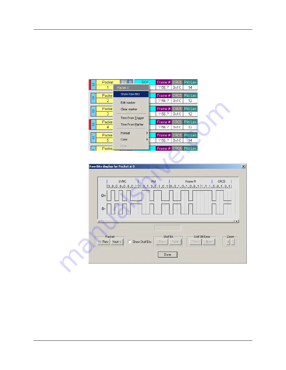
You can expand a specific packet to view the raw bits in detail. 

To view the raw bits: 

Step 1

Left-click 

Packet #

 for the packet to display the

 Packet 

menu: 

Step 2

Select 

Show Raw Bits

 to display the Raw Bits View for that packet: 

Along the top of the Raw Bits View is a linear strip of the logical bit values with 
corresponding field demarcations. Bit stuffing is displayed in color. Below the logical bit 
values is a representation of the D+/D- signaling complete with NRZ encoding. A scroll 
bar assists in navigation of larger packets. Two buttons under the label 

Packet 

are used 

to view previous or next packets. Two buttons under the label 

Zoom

 allow you to zoom 

in or out on packets.

Содержание Advisor

Страница 1: ...For Software Version 2 6 April 2008 PROTOCOL SOLUTIONS GROUP 3385 SCOTT BLVD SANTA CLARA CA 95054 LeCroy Advisor USB 2 0 Bus and Protocol Analyzer User Manual Manual Version 2 61 ...

Страница 2: ...igned to provide reasonable protection against harmful interference when the equipment is operated in a commercial environment This equipment generates uses and can radiate radio frequency energy and if not installed and used in accordance with the instruction manual may cause harmful interference to radio communications Operation of this equipment in a residential area is likely to cause harmful ...

Страница 3: ...ject to disposal and recycling regulations that vary by country and region Many countries prohibit the disposal of waste electronic equipment in standard waste receptacles For more information about proper disposal and recycling of your LeCroy product please visit www lecroy com recycle ...

Страница 4: ...USBAdvisor User Manual LeCroy Corporation ...

Страница 5: ...n Outs for the Data In Out Connector 13 Prototype Rework Area 13 PC Connection 13 Chapter 3 Quick Installation 15 3 1 Your First USB Recording 16 Capturing Your First CATC Trace 18 Trace View Features 19 Chapter 4 Detailed Installation 21 4 1 Advisor System Setup 21 4 2 USB Test Ports 23 4 3 AC Power Source 23 4 4 Advisor Program Installation 24 Loading the Advisor USB Drivers 24 Installing the Ad...

Страница 6: ...e Devices 49 6 11 Hide Chirps 49 6 12 Switch to Transactions View 50 6 13 View Decoded Transactions 52 Expanded and Collapsed Transactions 53 6 14 Switch to Split Transaction View 54 6 15 Switch to Transfer View 54 6 16 View Decoded Transfers 55 Expanded and Collapsed Transfers 55 6 17 Decoding Protocol Specific Fields in Transactions and Transfers 56 6 18 Switch to Host Wire Adapter Segment View ...

Страница 7: ...ndpoint RPipe to Class Vendor Decoding 97 Mapping Request DWA RPipe to Class Vendor Decoding 98 Mapping Endpoint DWA RPipes to Class Vendor Decoding 99 9 3 General Options 100 Decoding USB Device Requests 100 Decoding Standard Requests 101 Decoding Class Requests 102 Decoding Vendor Requests 102 Decoding Undefined USB WUSB Device Requests 102 Decoding using Endpoint Information 103 Changing the La...

Страница 8: ...Out In 132 11 7 Other Actions External Output Signals 133 11 8 Saving Recording Options 135 11 9 Recording Bus Data 136 11 10 Merging Trace Files 137 Chapter 12 Updates 139 12 1 Software Firmware and BusEngine Revisions 139 12 2 Software Updates 140 12 3 BusEngine and Firmware Updates 141 Updating the Firmware 141 Automatic Updates 141 Manual Updates to BusEngine and Firmware 143 Manually Upgradin...

Страница 9: ...bles and connections to capture and display Hi Speed and Classic Speeds USB 2 0 bus traffic 1 1 Features General Fully compliant with USB 2 0 specification Supports Link Power Management Extension to USB 2 0 specification Flexible design reconfigurable hardware for future enhancements Supports all USB speeds High Speed Full Speed and Low Speed User friendly CATC Trace Interface that displays bus t...

Страница 10: ...ransaction special tokens i e ERR SPLIT PING NYET DATA2 MDATA CATC Trace displays and enumerates new USB2 0 Micro Frames Three forms of triggering Snapshot Manual and Event Automatically detects and captures high full and low speed traffic Adjustable buffer size from 0 1MB to 128MB Versatile triggering bit wise value and mask data patterns up to sixteen bytes wide for Setup transactions and data p...

Страница 11: ... calculations Each marker can contain unique comments Hide start of frame SOF packets as well as hide any packet or transaction Search for a specific PID Change bit order for all fields except Data Length Time and Packet MSB LSB or LSB MSB Detects and alerts the user to every potential bus error protocol violation and com binations thereof High resolution accurate time stamping of bus packets timi...

Страница 12: ...Protocol errors are automatically detected and highlighted in red The display is customizable allowing the user to control the color scheme and the formatting of field contents A hide feature allows users to enable the suppression of SOF packets and user defined packets or fields that may be uninteresting in a given context Display formats can be named and saved for later use Pop up tooltips annot...

Страница 13: ...luding wrong packet length data payload violation and packet termination not on a byte boundary 1 5 Real Time Event Triggering and Capture Filtering No attribute of a bus and protocol Analyzer is more important than its capacity for extracting useful information from a crowded stream of bus traffic The ability to accurately identify and selectively record transactions of interest is the trait most...

Страница 14: ...ertain types of events for recording Without this feature a designers must scroll through potentially megabytes of recorded data to locate a specific sequence or occurrence of a sequence that can take hours to locate before being able to begin analyzing the data of interest 1 7 BusEngine Technology LeCroy s BusEngine Technology is at the heart of the new Advisor USB 2 0 Analyzer The revolutionary ...

Страница 15: ...erface as color coded packets that can be searched for specific data errors or other desired conditions The Advisor USB2 0 Bus Protocol Analyzer is the ideal USB tool used in conjunction with any Microsoft Windows 2000 Windows XP Windows Vista 32 or Windows Vista 64 desktop or portable PC in a USB development lab environment Note Support for Windows 2000 will end on January 1 2008 The Advisor Anal...

Страница 16: ...mmended to have physical RAM twice the size of the recording buffer setup 256 MB or more Minimum is 128 MB of RAM At least 20 MB of free hard disk space is required for the installation Additional disk space is needed for storing the recorded data in files during the recordings process can be as much as 150MB when recording a full buffer size Display Resolution of 1024 x 768 with at least 16 bit c...

Страница 17: ...ush button allows a manual Trace capture After beginning a recording session press the Manual Trigger switch to force a Trigger condition The session completes when a specified post Trigger amount of bus data is recorded or when you manually stop a recording session Detach Device push button allows a momentary disconnection of the device from the host on the Classic Speeds port This is especially ...

Страница 18: ... mm 2 0A 250 V fast acting glass fuse Warning For continued protection against fire replace fuse only with the type and rating specified above USB type B host computer connector Data In Out DB 9 9 pin external interface connector Warning Do not open the Advisor Analyzer enclosure There are no operator serviceable parts inside Refer servicing to LeCroy ...

Страница 19: ...Out 9 pin DB Weight 2 8 lbs 1 2 kg Operating Temperature 0 to 55 C 32 to 131 F Storage Range 20 to 80 C 4 to 176 F Operating Humidity 10 to 90 non condensing Operating Altitude Up to 6560 feet 2000 meters Power on off Manual Trigger Forces trigger event Detach Device Detaches the device from the classic speed connection Power PWR Illuminated when the Analyzer is powered on Recording REC Illuminate...

Страница 20: ...erface Breakout Board is an accessory that allows convenient access to several potentially useful standard fast TTL output and input signals It also offers a simple way to connect logic Analyzers or other tools to the Advisor Analyzer unit Four ground pins and one 5 volt pin are provided Figure 2 3 External Interface Breakout Board The Breakout Board connects via a cable to the Data In Out connect...

Страница 21: ...for making custom circuits for rapid development The area consists of plated through holes 20 columns wide by 27 rows long The top row of holes is connected to GND and the bottom row is connected to 5V The remaining holes are not connected Use the rework area to insert custom components and wire wrap their respective signal power and ground pins PC Connection Use the LONGEST 6 foot 2 meter of the ...

Страница 22: ...Chapter 2 General Description USBAdvisor User Manual 14 LeCroy Corporation ...

Страница 23: ...the USB port on the back of the Analyzer to the PC for analysis by using the LONG 6 foot 2 meter USB cable Step 3 Insert the CD ROM Step 4 Turn on the Power switch located on the rear of the Analyzer Step 5 Click NEXT when you see the Add New Hardware Wizard window Step 6 Follow the on screen Plug and Play instructions Step 7 Click Finish when you see the message that says Windows has finished ins...

Страница 24: ...ecording After installing and launching the software you can test Advisor by performing the following steps Step 1 Connect a USB cable to each of the two connectors on the Advisor module then connect the other ends to the USB device under test and USB host system Step 2 Select Recording Options under Setup on the Menu Bar ...

Страница 25: ...ick on the Tool Bar Advisor starts to record the USB traffic immediately After 1 MB of traffic is recorded the Analyzer uploads the data and displays the packets in the trace window Step 7 If you wish to terminate the recording before the snapshot automatically completes click on the Tool Bar When the recording session is finished the traffic is uploaded from the Analyzer to the hard drive on your...

Страница 26: ...rding for future reference select Save As under File on the Menu Bar OR Click on the Toolbar You see the standard Save As screen Step 9 Give the recording a unique name and save it to the appropriate directory Capturing Your First CATC Trace After a moment the recording terminates and the results display ...

Страница 27: ...d time stamped with a resolution of 16 67 ns and highlighted to show the transmitted speed low speed full speed or high speed Display formats can be named and saved for later use Pop up Tool Tips annotate packet fields with detailed information about their con tents Data fields can be collapsed to occupy minimal space in the display which can in turn be zoomed in and out to optimize screen utiliza...

Страница 28: ...Chapter 3 Quick Installation USBAdvisor User Manual 20 LeCroy Corporation ...

Страница 29: ...er is a stand alone unit configured and controlled through a personal computer USB port It can be used with portable computers for field service and maintenance as well as with desktop units in a development environment It is easily installed by connecting a cable between the computer s USB port and the Analyzer s USB port Figure 4 1 USB Advisor Connection The Advisor Analyzer provides on the fly ...

Страница 30: ... data or timing information to be recorded along with bus traffic Real time event detection information is available via an external DB 9 connector The Advisor software provides powerful search functions that enable investigation of particular bus events and allow the software to identify and highlight specific events In addition to immediate analysis you can print any part of the data Use the Sav...

Страница 31: ...usive high impedance tap Because of the poor signal quality in the middle of a USB cable LeCroy recommends using the shortest possible cables so that the total length of both cables together is less than 6 feet The USB cables provided with your Analyzer meet this requirement When longer cables are used the Analyzer may record incorrect data 4 3 AC Power Source To turn on the system Step 1 Connect ...

Страница 32: ...ear of the Analyzer and to the personal computer The host operating system detects the Analyzer and begins to install the USB driver Step 4 When Windows prompts you for a file browse to the CD ROM Installing the Advisor Application Program To install the Advisor program follow these steps Step 1 Insert the Advisor CD ROM into your computer Step 2 Click Install Software Step 3 Follow the installati...

Страница 33: ...or When used without Advisor the program functions in a Trace Viewer mode to view analyze and print captured protocol traffic When the program is used with the Advisor Protocol Analyzer attached to the computer you can set trigger conditions record monitor and analyze the activity of your USB bus 4 6 Making a Recording After installation the software is configured to make a Snapshot recording of U...

Страница 34: ...Chapter 4 Detailed Installation USBAdvisor User Manual 26 LeCroy Corporation ...

Страница 35: ...le created with any of these Analyzers displays a screen asking if you want to convert the old file to the new format under the name convert usb When the program is used with the USB Advisor Analyzer attached to the computer you can monitor and analyze the activity of your USB branch from either of the USB ports on the front of the Analyzer 5 1 Starting the Advisor Program To start the USB Advisor...

Страница 36: ...r generator file Saves trace as text file in Packet View Format Saves trace as a comma separated values text file for use with Microsoft Excel Saves trace as script file that can be used by a Generator to generate a trace Exports packets to Device Emulation files This option does not export transactions Exports Transfer data as text or binary file Merge Trace Files Merges two simultaneously record...

Страница 37: ... Summary Summarizes the numbers and types of errors packets transactions split transactions and transfers that occurred in the open trace Bus Utilization Displays graphs of packet length bus usage and bus usage by device Search Go to Trigger Positions the display to show the first packet that follows the trigger event Go to Packet Transaction Transfer Positions the display to the packet transactio...

Страница 38: ...oss recordings Packet Level Displays Packets Transaction Level Displays Transactions Split Transaction Level Displays Split Transactions Transfer Level Displays Transfers HWA Segment Level Displays Host Wire Adapter Segments HWA Transfer Level Displays Host Wire Adapter Transfers DWA Segment Level Displays Device Wire Adapter Segments DWA Transfer Level Displays Device Wire Adapter Transfers PTP T...

Страница 39: ...the buttons on the toolbar to not match their intended function You can reset the toolbar by performing the following steps Step 1 Select View Toolbars from the menu bar Help Help Displays online help Help Topics Displays online help You can also select F1 Update License Opens a dialog box for updating your LeCroy license Display License Information Displays information related to licensing About ...

Страница 40: ...User Manual 32 LeCroy Corporation Step 2 Select Customize from the sub menu to display the Customize dialog box Step 3 Select the Toolbars tab to list the toolbars Step 4 Click the Reset All button The toolbar resets to the factory defaults ...

Страница 41: ...ecodes Preview Find Print Find Next Setup Record Options File Information Report Setup Display Options Error Report Start Recording Timing and Bus Usage Calculations Stop Recording Traffic Summary Zoom In Bus Utilization Zoom Out Display Packets Wrap Display Transactions Hide SOFs Display Split Transactions Starts the Trace Navigator Display Transfers Partial Upload Display Host Wire Adapter Segme...

Страница 42: ...isplay Options When the Trigger Position is reached the progress indicator wiggles as it waits for the trigger After the trigger occurs the field to the right of the Trigger Position fills in the after Trigger color specified in the Display Options When recording is complete the upper half of the progress indicator fills in white indicating the progress of the data upload to the host computer You ...

Страница 43: ...g the default file name data usb If two channels of traffic are recorded Advisor creates two files data usb and data_classic usb You can specify a file name in the Recording Options dialog box To abort the upload process Press Esc on your keyboard OR Again click in the Tool Bar Note While uploading is in progress clicking the stop button again brings up a dialog opens a dialog that allows you to d...

Страница 44: ...y positioned second from the top of the display If the recording did not result from a Trigger Event the display begins with the first packet in the traffic file Recording Activity During recording the fourth segment from the left of the Status Bar displays Recording activity as a series of vertical bars The more vertical bars that are displayed the greater the amount of activity being recorded If...

Страница 45: ...allowing fewer but larger packet fields per screen Click on the Tool Bar Zoom Out Zoom Out decreases the size of the displayed elements allowing more but smaller packet fields per screen Click on the Tool Bar Wrap Select Wrap to adjust the Trace View so that packets fit onto one line If a packet is longer than the size of the window the horizontal scroll bar can be used to see the hidden part of t...

Страница 46: ...trl F Jump to First Packet Ctrl Home Jump to Last Packet Ctrl End Go to Any Error Shift E Go to Channel 0 Ctrl Shift 0 Go to Channel 1 Ctrl Shift 1 PID Go to ACK Shift A Go to DATA0 Shift 0 Go to DATA1 Shift 1 Go to DATA2 Shift 2 Go to DATAx Shift D Go to IN Shift I Go to MDATA Shift M Go to NAK Shift N Go to NYET Shift Y Go to OUT Shift O Go to PING Shift G Go to PRE ERR Shift P Go to SETUP Shift...

Страница 47: ... Go to Full Speed J Shift J Go to Full Speed K Shift K OTG Go to SRP Ctrl Q Go to HNP Shift H Go to VBus Voltage Change Shift V Go to OTG Host A Ctrl Shift A Go to OTG Host B Ctrl Shift B Misc Marker Menu Ctrl M Open File Ctrl O Print Ctrl P Record Ctrl R Stop Recording Ctrl T Open Display Options dialog Ctrl Shift D Open Recording Options dialog Ctrl Shift R Hide SOFs Ctrl Shift S Hide NAKs Ctrl ...

Страница 48: ...Chapter 5 Software Overview USBAdvisor User Manual 40 LeCroy Corporation ...

Страница 49: ...s recorded time stamped with a resolution of 16 67 ns and highlighted to show the transmitted speed low speed full speed or high speed Display formats can be named and saved for later use Pop up Tool Tips detail the contents of packet fields Data fields can be collapsed to occupy minimal space in the display and you can zoom in and out to optimize screen utilization The display software can operat...

Страница 50: ...ket To place a marker on a packet Step 1 Left click Packet for the packet you wish to mark to display the Packet menu Step 2 Select Set Marker to display the Edit Marker Comment window Step 3 Enter a comment about the packet Step 4 Click OK A marked packet is indicated by a vertical red bar along the left edge of the packet block ...

Страница 51: ...ts associated with a packet marker Step 1 Left click Packet for the chosen packet to display the Packet menu Step 2 To edit the Marker Comment select Edit Marker Comment to display the Edit Marker Comment window Edit the comment then click OK Step 3 To clear a Marker click Clear Marker The vertical red Marker bar disappears ...

Страница 52: ...he Raw Bits View for that packet Along the top of the Raw Bits View is a linear strip of the logical bit values with corresponding field demarcations Bit stuffing is displayed in color Below the logical bit values is a representation of the D D signaling complete with NRZ encoding A scroll bar assists in navigation of larger packets Two buttons under the label Packet are used to view previous or n...

Страница 53: ...sing the Stuff Bit Buttons The bottom center of the Raw Bits View contains a checkbox and buttons for viewing Stuff Bits Select the Show Stuff Bits checkbox and then click the Prev button to view previous stuff bits in a trace Click the Next button to view show the next stuff bits in a trace Under Stuff Bit Error click the Prev button to view previous stuff bit errors in a trace and click Next to ...

Страница 54: ... the Expand Collapse Data Field Arrows Data Fields can be easily expanded or collapsed by clicking the small triangular arrows on the left side of the data field Double Clicking to Expand Collapse Data Fields Data fields can also be expanded or collapsed by double clicking anywhere in the data field Expanding or Collapsing All Data Fields Expand or collapse all data fields by holding down the butt...

Страница 55: ...you want to expand or collapse If your Data Trace View is currently expanded you see the Collapse Data menu If your Data Trace View is currently collapsed you see the Expand Data menu Step 2 Select the desired Expand Data or Collapse Data menu item The Trace View is repositioned with the selected packet s adjusted in the format you have specified Expand or Collapse All Data Fields All data fields ...

Страница 56: ... 1 Click in the data field to open the Data Field menu Step 2 Select View Data Block to open the Data Block dialog box The View Data Block window has options for displaying the raw bits in different formats Format Lets you display data in Hex Decimal ASCII or Binary format Show Per Line Lets you control how many bits are displayed per line Bit Order Most Significant Bit or Least Significant Bit ...

Страница 57: ... from a Trace View by clicking the Hide SOF Packets button on the Tool Bar Click to hide all SOF packets 6 9 Hide NAKs You can hide NAKs that may be uninteresting in a given context from a Trace View by clicking the Hide NAKs button on the Tool Bar Click to hide all NAK packets 6 10 Hide Devices Click the to open a tear off window that allows you to select any address endpoint combination that you...

Страница 58: ...lay mode is Packet View Before you can view decoded transactions you must switch from Packet View to Transactions View To select Transactions View Step 1 Click on the toolbar to redraw the Trace View to display transactions Note This menu selection displays a check mark next to Show USB transactions when you have selected it When you want to switch back to Packet View mode right click anywhere in ...

Страница 59: ...Chapter 6 Reading a Trace LeCroy Corporation 51 To switch to Transaction View from the Menu Bar Step 1 Select Display Options under Setup to display the Display Options General window Step 2 Check Transactions Step 3 Click OK ...

Страница 60: ...o display decoded transactions in the colors and format you selected When you instruct the Analyzer to display USB transactions the components of each transaction are collected from the current recording and are grouped and indented below each decoded transaction Each row shows a transaction with a unique numeration a label and color coded decoding of important data ...

Страница 61: ...ansaction in expanded format Note The Expand Collapse transaction feature operates as a toggle when one format is active the other appears as an option on the Expand Collapse drop down menu To collapse a transaction perform the same operation and select Collapse This Transaction Note that you can choose to expand or collapse Only the selected Transaction OR All Transactions It is not necessary to ...

Страница 62: ... transfers can be one of four kinds Control Interrupt Bulk and Isochronous Advisor is capable of displaying all four types The default display mode is Packet View Before you can view decoded transfers you must switch from Packet View or Transaction View to Transfer View To select Transfer View Step 1 Click on the toolbar to redraw the Trace View screen to display Transfers Note Selecting Show USB ...

Страница 63: ...nsfer are collected from the current recording and are grouped below each decoded transfer Each transfer row shows a transfer with a unique numeration a label and color coded decoding of important data To view decoded transfers select Transfer Level from the View menu Expanded and Collapsed Transfers You can expand a specific transfer to view its parts which are grouped and indented below the tran...

Страница 64: ...f a transfers Double click in the Transfer number field to toggle back and forth between collapsed and expanded views 6 17 Decoding Protocol Specific Fields in Transactions and Transfers When transfers or transactions are displayed the fields in setup transactions or control interrupt and Bulk transfers by default do not get decoded and are shown in hexadecimal values The exceptions are setup tran...

Страница 65: ...nd a host wire adapter To view host wire adapter segments switch to the Host Wire Adapter Segment trace viewing level To select the Host Wire Adapter Segment trace viewing level Click on the toolbar OR Select View Show Host Wire Adapter Segment OR Select Setup Display Options to display the Display Options window check HWA Segment and then click OK The program redraws the trace view ...

Страница 66: ...e wire adapter To view device wire adapter segments switch to the Device Wire Adapter Segment trace viewing level To select the Device Wire Adapter Segment trace viewing level Click on the toolbar OR Select View Show Device Wire Adapter Segment OR Select Setup Display Options to display the Display Options window check DWA Segment and then click OK 6 21 Switch to Device Wire Adapter Transfer View ...

Страница 67: ...ction OR Select Setup Display Options to display the Display Options window check PTP Transaction and then click OK 6 23 Switch to PTP Object Transfers A logical object on a device has a unique 32 bit identifier object handle The object handle is also unique for the session defined below An object transfer contains all the transactions for an object handle In PTP all of an object handle s PTP Tran...

Страница 68: ...on A session contains all object transfers and their transactions plus all transactions that do not belong to object transfers between an OpenSession operation and a CloseSession operation For PTP all PTP Object Transfers and all PTP Transactions that occur from the OpenSession operation to the CloseSession operation is a single PTP Session The PTP Session trace viewing level is the highest PTP le...

Страница 69: ...ically to the right of the trace window when opened The Navigator bar represents different types of trace information in the order of the packets The top of each bar corresponds to the first packet in the trace and the bottom corresponds to the last packet The Navigator bar is made up of three parts Pre and Post Trigger traffic Errors and Types of Traffic At any time a line in the navigator bar of...

Страница 70: ...s traffic information in the Navigator Legend Shows or hides Trigger Error and Traffic Type categories in the Navigator Set Range to Whole Trace Sets packet range to the entire trace Set range near Packet number Sets the packet range near the packet where your mouse pointer is positioned in the Navigator bar Recent Ranges Displays a history of ranges that were previously selected ...

Страница 71: ...ld take precedence and the Navigator would show the black bar 6 26 Edit Comment You can create view or edit the 100 character comment field associated with each Trace file The comments are visible in the Windows Explorer if the Comments attribute is included in the Details view Step 1 Select Edit Comment under File on the Menu Bar to display the Edit comment for Trace file window Step 2 Create vie...

Страница 72: ...Chapter 6 Reading a Trace USBAdvisor User Manual 64 LeCroy Corporation ...

Страница 73: ... packet number marking or content To view the Search options Click Search in the Menu bar to display the Search drop down menu 7 1 Go to Trigger Note Go to Trigger is enabled only when a trigger has created the traffic file To display a Trigger Event Select Go to Trigger under Search on the Menu Bar The Trace View is repositioned to the first packet following the Trigger event This packet is at th...

Страница 74: ...iew is repositioned with the selected packet at the top of the screen 7 3 Go to Marker To instruct the Analyzer to display a marked packet Step 1 Select Go to Marker under Search on the Menu Bar to display a drop down menu listing the marked packets in that Trace View Step 2 Select the desired packet from the displayed list The Trace View is repositioned with the selected packet at the top of the ...

Страница 75: ... Traces LeCroy Corporation 67 7 4 Go To The Go To feature takes you directly to an event in a Trace Step 1 Select Go To under Search on the Menu Bar to display the Go To drop down menu Step 2 Select an event and enter the necessary information ...

Страница 76: ...Chapter 7 Searching Traces USBAdvisor User Manual 68 LeCroy Corporation Packet IDs PIDs Select the type of packet ...

Страница 77: ...oration 69 Errors The Errors menu allows you to search for five different types of error PID CRC5 CRC16 Packet Length and Stuff Bits Menu items appear in bold if they are present in the trace or grayed out if not present in the trace as shown in the example below ...

Страница 78: ...engths are displayed in Bytes in a drop down menu as shown below Selecting a length moves the display to the next instance of that packet length Addr Endp The Addr Endp feature allows you to search for the next packet which contains a particular address and endpoint All available address endpoint combinations are displayed in the pull down menu ...

Страница 79: ...r Manual Chapter 7 Searching Traces LeCroy Corporation 71 Bus Conditions Allows you to search by bus conditions such as traffic speed reset and suspend All available bus conditions are displayed in the pull down menu ...

Страница 80: ...s USBAdvisor User Manual 72 LeCroy Corporation On The Go Allows you to search for USB On The Go conditions USB On The Go conditions are listed in the drop down menu Channel Allows you to search by 0 Hi Speed and 1 Classic Speed ...

Страница 81: ...ackets with x AND y Union creates OR statements such as Find all packets with x OR y You can also perform searches whereby packets or events are excluded from a trace The Exclusion allows searches to be conducted To perform a search Step 1 Select Find under Search on the Menu Bar OR Click in the Tool Bar to display the User Defined Find Events screen Step 2 Select Packets Transactions Split Transa...

Страница 82: ...lect Union AND Exclusion Exclude packets with ANY of the following fields or Intersection AND Exclusion Exclude packets with ALL of the following fields Step 5 If desired set the search Direction and Origin Step 6 Click OK After the search finishes the packets meeting the search criteria are displayed 7 6 Find Next To apply the previous Find parameters to the next search Select Find Next under Sea...

Страница 83: ...hat information to display in CATC Traces using the Display Options window To open the Display Options window Select Display Options under Setup on the Menu Bar OR Click on the Tool Bar You can select General Color Format Hiding and Level Hiding display options The following sections describe these display options ...

Страница 84: ...e beginning in a column on the left side of the Trace View At the end in a column on the left side of the Trace View or Merge with Packet Transaction Translation Selecting this option allows easier comparison with previous or following timestamps Expand Packet Data Fields by default Displays packet data fields in expanded mode If this option is not selected packet data fields display in collapsed ...

Страница 85: ...rs and Errors Bus Utilization Displays the Bus Utilization window including Packet length Bus usage and Bus usage by device Navigator Displays the Navigation bar including Pre Post Triggers Errors and Types of Traffic Trace Viewing Level Displays Packets Transactions Split Transactions Transfers Host Wire Adapter Segments Host Wire Adapter Transfers Device Wire Adapter Segments Device Wire Adapter...

Страница 86: ...Chapter 8 Display Options USBAdvisor User Manual 78 LeCroy Corporation 8 2 Color Format Hiding Display Options To modify the colors formats and hiding options select the Color Format Hiding tab ...

Страница 87: ...olor combinations are appropriate for most graphic systems You can alter any color To specify a color for an information type in the Color Format Hiding tab select a row such as Data in the Group and Color column and expand it Select a data type such as Data Length in the Group then select a color in the Color section using Standard or Custom colors Use a bright color for each important field ...

Страница 88: ...the program has a default data format Examples of number data formats are Bin binary Dec decimal and Hex hexadecimal Examples of date and time data formats are Hex uFrame Dec uFrame Date Time Time Bit Time seconds microseconds and nanoseconds An example of a text data format is ASCII You can alter some data formats To specify a data format for an information type in the Color Format Hiding tab sel...

Страница 89: ...ns are MSB to LSB or LSB to MSB Hiding Display Options By default no data is hidden You can hide any group of data and any type of data You can hide transactions SOFs NAKs High Full or Low Speed packets traffic from one or both recording channels and Addresses and Endpoints To hide one or more fields select the Group and Data type in the Group and Color column then click the Hidden checkbox in the...

Страница 90: ...splay Options By default no data packets transactions or bus conditions are hidden You can hide Start of Frame packets NAK ed transactions Chirp and SEO Bus conditions High Full or Low Speed packets Channel 0 or Channel 1 packets Select the Level Hiding tab then select the data types to hide ...

Страница 91: ...tension The program adds the opt extension The file must have an opt file name extension To load a previously saved opt file click Load and select a file name To save the current Display Options values in the default opt options file for use as the default display options click Save as Default Do not delete the default opt file To apply the current Display Options values click Apply The Display Op...

Страница 92: ...Chapter 8 Display Options USBAdvisor User Manual 84 LeCroy Corporation ...

Страница 93: ...pt Decoding on page 147 Note The dec files listed in the following table are in the Scripts directory under the installation directory USB Decode USB Decoder Name USB IF Base Class Codes Sub Class Proto col ID Audio Class decoding 2 0 AudioClass Audio1 0Requests dec AudioClass Audio2 0Requests dec Audio 01h Communications and CDC Control Direct Line Control Model Abstract Control Model Telephone C...

Страница 94: ... PTPStillInterrupt dec PTP Still Image 06h 01h 01h Printer Printer Printer_req dec Printer 07h 01h xxh Mass Storage Mass Storage 08h SCSI Bulk Protocol MassStorageClass MS_BulkOnly_Requests dec MassStorageClass MS_BulkOnlySCSIInEndpoint dec MassStorageClass MS_BulkOnlySCSIOutEndpoint dec MassStorageClass MS_BulkOnlySCSIOutEndpoint dec Mass Storage SCSI Bulk 08h UFI floppy CBI Protocol MassStorageC...

Страница 95: ...ochIn_wPW dec Communications CDCDataIsochIn_wPW_wCTE dec Communications CDCDataIsochOut_wCTE dec Communications CDCDataIsochOut_wPW dec Communications CDCDataIsochOut_wPW_wCTE dec 0Ah 00h Smart Card CCID SmartCard CCIDBulkIn dec SmartCard CCIDBulkOut dec SmartCard CCIDInterrupt dec SmartCard CCID_req dec SmartCard ICCDBulkIn dec SmartCard ICCDBulkOut dec SmartCard ICCDInterrupt dec SmartCard ICCD_...

Страница 96: ...andard StandardRequests dec IEEE IEEECompanies dec Virtual VirtualDATAIn dec Virtual VirtualDATAOut dec Virtual VirtualUARTIn dec Virtual VirtualUARTOut dec AssociationFrameworks WUSB_CableBasedAssociation dec IrDA Bridge ATAPI IP HTTP Personal Healthcare Devices PersonalHealthcare PersonalHealthcareRequest dec PersonalHealthcare PersonalHealthcareDescriptors inc PersonalHealthcare PersonalHealthc...

Страница 97: ...ping Request Recipient to Class Vendor Decoding To assign a decoding group to a request recipient Step 1 Click the Apply Decoding Scripts button on the Toolbar OR Left click the Control Transfer field to display the USB Device Request menu Step 2 Select Map Request Recipients to Class Vendor Decoding to display the Request Recipient and Endpoints dialog box The Recipient field shows all Class and ...

Страница 98: ...ss Requests CCID Requests Communication Class Requests HCI Command HID Class HID Class Requests Hub Class Requests ICCD Ver A Requests ICCD Ver B Requests IrDA Bridge Class Requests Mass Strg Bulk Only Requests Mass Strg Class UFI CBI Requests Printer Class Requests RNDIS Communication Class Requests Standard Requests Still Image PTP MTP PictBridge Class Requests Video 1 0 Class Requests Video 1 1...

Страница 99: ...elect a decoding group OR Select No Decoding if you do not want any specific decoding Step 6 Repeat the previous steps for additional recipients Step 7 To retain a mapping from trace to trace DURING an application session select the Keep Across Recordings checkbox Step 8 Click OK ...

Страница 100: ... menu Step 2 Select Map Endpoint to Class Vendor Decoding to display the Request Recipients and Endpoints dialog box Step 3 Click the Endpoints tab to display the Endpoints dialog box The Endpoint field Endp shows all Endpoints found in the trace file The displays shows the Host Address and Direction for the recipient On the right are the names of Class Vendor Endpoint Decoding groups currently as...

Страница 101: ...r CCD Data Bulk Out w Prot Wrapper CCD Data Isoch Out w Cmd Wrapper CCD Data Isoch Out w Prot Cmd Wrapper CCD Data Isoch Out w Prot Wrapper Display DATA HCI data out HCI SCO out HTTP Out Endp ICCD Bulk Out Message IP_ET0800 Internet Protocol Out Endp IPv6_ET0800 Internet Protocol Out Endp IrDA Bridge Out Endp Mass Strg Bulk Only SCSI Out Endp Mass Strg UFI_CBI Bulk Out Endp RNDIS_PACKET_MSG Bulk O...

Страница 102: ...otification Display DATA HCI data in HCI event HCI SCO in HID In Endp HTTP In Endp Hub Class Status Change Endp ICCD Bulk In Message ICCD Interrupt Message IP_ET0800 Internet Protocol In Endp IPv6_ET0800 Internet Protocol In Endp IrDA Bridge In Endp Mass Strg Bulk Only SCSI In Endp Mass Strg CBI Interrupt Endp Mass Strg UFI_CBI Bulk In Endp Mass Strg UFI_CBI Interrupt Endp RNDIS_PACKET_MSG Data In...

Страница 103: ... of decoding OR Select No Decoding if you do not want any specific decoding Step 7 Repeat the previous steps for any additional endpoints you would like to map Step 8 To retain a mapping from trace to trace DURING an application session select the Keep Across Recordings checkbox Step 9 Click OK ...

Страница 104: ...og box The Recipient field shows all Class and Vendor Request recipients found in the trace file The RPipe field shows all Class and Vendor Request RPipes found in the trace file The displays shows the Otg Host HWA address and Type Class or Vendor for the recipient On the right are the names of Class Vendor Decoding groups currently assigned to recipients If blank no decoding is assigned for a rec...

Страница 105: ...ipes found in the trace file The displays shows the Otg Host HWA address and Direction for the recipient On the right are the names of Class Vendor Endpoint Decoding groups currently assigned to endpoints If blank no decoding is assigned for a recipient Step 4 Select an endpoint RPipe Step 5 Display the Class Vendor Endpoint Decoding drop down menu The Class Vendor Endpoint Decoding options are th...

Страница 106: ...st DWA RPipes dialog box The Recipient field shows all Class and Vendor Request recipients found in the trace file The RPipe field shows all Class and Vendor Request RPipes found in the trace file The displays shows the Otg Host HWA address and Type Class or Vendor for the recipient On the right are the names of Class Vendor Decoding groups currently assigned to recipients If blank no decoding is ...

Страница 107: ... shows all RPipes found in the trace file The displays shows the Otg Host HWA address and Direction for the recipient On the right are the names of Class Vendor Endpoint Decoding groups currently assigned to endpoints If blank no decoding is assigned for a recipient Step 4 Select an endpoint DWA RPipe Step 5 Display the Class Vendor Endpoint Decoding drop down menu The Class Vendor Endpoint Decodi...

Страница 108: ... decoding click Refresh Decoding for this Trace File Use this option to reanalyze all transactions Step 3 To use the previous decoding click Load most recent decoding mapping This option loads the most recent mapping of endpoints requests to decoding types that was done on a previous trace If the endpoints of the new trace are the same as the last one mapped the mappings are applied to the current...

Страница 109: ... Find What field To use a case sensitive search check Match Case To find only the exact word check Match Whole Word Only You can search Up or Down To search click Find Next Step 3 To save the View Fields text box as an HTML file click the Save As button enter a file name in the Save As dialog box then click Save Step 4 To view the previous or next Transfer Control field request of the same request...

Страница 110: ...vice Request menu select Decode Request to display the View Fields for Class Requests text box The following figure shows a Wire Adapter Class Requests decoding Decoding Vendor Requests To decode a vendor request From the USB Device Request menu select Decode Request to display the View Fields for Vendor Requests text box An example of a vendor request is USB Advisor Command Set Decoding Undefined...

Страница 111: ...dp text box The following figure shows a Wire Adapter Data Transfer Out Endp decoding Changing the Layout of Decode Requests In the View Fields windows the Decoding Information and the Descriptor information blocks following the Request Summary information have the following columns Field such as bRequest wValue wIndex bLength bDescriptorType wTotalLength Length in bits Offset in bits Decoded hex ...

Страница 112: ... Fields Dialog Layout Dialog Box Step 2 To display the available columns of data use the checkboxes for Length Offset Decoded Hex Value and Description You can Check All or Uncheck All Step 3 To show only the fields of Collapsed mode check Show only fields specified for view in collapsed mode Step 4 To retain settings for future viewing of Decode Request fields check Use these settings when View F...

Страница 113: ...USBAdvisor User Manual Chapter 10 Reports LeCroy Corporation 105 Chapter 10 Reports The Report menu provides several reports to assist you in analyzing USB traffic recorded by the Analyzer ...

Страница 114: ...Bar OR Click in the Tool Bar to display the File Information screen The File Information report provides information about how the recording was made what the buffer settings were the license number of the Analyzer that created the file what the trigger options were the user s license information and what version of all the Analyzer hardware was used to make the recording ...

Страница 115: ...l errors analyzed throughout the recording Select Error Summary under Report in the Menu Bar OR Click in the Tool Bar to display the Errors pane Navigate to an error within the recording by clicking the number of the packet containing the error Use the arrows to cycle though each occurrence of a particular error ...

Страница 116: ...eCroy Corporation 10 3 Timing Calculations The Timing Calculator is used to measure timing between any two packets Select Timing Calculations under Report in the Menu Bar OR Click in the Tool Bar to display the Timing and Bus Usage Calculator screen ...

Страница 117: ...y Traffic Summary summarizes the numbers and types of packets transactions and so on that occurred in the open trace To run Traffic Summary select Report Traffic Summary or click the button marked The program prompts you to specify a range of packets then displays the following window ...

Страница 118: ...0 LeCroy Corporation 10 5 Bus Utilization The Bus Utilization window displays information on bandwidth use for the two recording channels To open the Bus Utilization window select Report Bus Utilization or click the button to display three graphs ...

Страница 119: ...Drag zoom Click diagonally to select and zoom in on part of the graph Full Screen Select Range View Settings opens a sub menu with options for formatting the display See Click the View Settings button to open a menu with options for formatting the display below Sync and Graph areas If two or more graphs are displayed this button synchronizes the graphs to one another Once synchronized the position...

Страница 120: ...k marks along the x axis of each graph Show Plumb Line Displays a vertical line that connects the cursor to the horizontal axis As you move the mouse the status bar shows the packet and time frame to which the cursor points Status Opens a submenu with the following options Bar Displays a status bar at the bottom Tooltip Displays a tooltip if you position the cursor over a field of the graphs None ...

Страница 121: ...USBAdvisor User Manual Chapter 10 Reports LeCroy Corporation 113 Fonts and Colors Opens the View Options dialog box for setting graph fonts and colors ...

Страница 122: ...ization window Step 1 Click the button to open the Graph Areas menu Step 2 Select the data you want to appear in the Graph Areas window Step 3 To make a new graph click New To change properties in the Bus Utilizations graph Step 1 In the Graph Areas menu select what you want your graph to display then click OK Step 2 To make a new graph click New ...

Страница 123: ... Recording Options to create and change various features that control the way information is recorded by the LeCroy USB Advisor Analyzer To open the Recording Options menu Select Recording Options under Setup on the Menu Bar OR Click on the Tool Bar to display the Recording Options window at the General tab ...

Страница 124: ... begins when is clicked and ends when either the selected buffer size is filled or the button is pressed Manual Trigger A Manual Trigger is a recording whose trigger point is caused by pressing the trigger button on the front panel Recording begins when you click on the Tool Bar Recording continues in a circular manner within the limits set by the buffer size Recording ends when is clicked on the ...

Страница 125: ...re is the one to be used for Triggering Filtering Buffer Size You can adjust the size of the recording buffer from 0 1 megabytes to 128 megabytes The Recording Type option determines how this buffer is used Although there are 128 megabytes of physical memory in the Analyzer the efficiency of the recording is about a 2 1 ratio of physical memory to actual USB traffic Shorter USB packets yield a sli...

Страница 126: ...an be very descriptive such as Trigger on High Speed traffic when CRC errors occur To create a new Recording Options name Step 1 Enter a comment for the new file in the Options Name field Step 2 Click Save to display the Save As window Step 3 Specify a filename rec Step 4 Click Save To load a Recording Options name Step 1 Click Load to display the Open window Step 2 From the list of rec files sele...

Страница 127: ...hin the corresponding Event Group As details are selected other Event Group details may become grayed out because of limited hardware resources in the Analyzer Information about the resources available is displayed below the Event Group details When a detail is grayed out it is inactive and cannot be selected If an Event Group remains inactive the current version of the application or BusEngine do...

Страница 128: ...Identifiers window The Packet Identifier PID field lists the available packet types Select up to three packet types to use as a Recording Trigger Token Patterns Select Token Patterns under Event Groups to display the Token Patterns window Specify up to three combinations of Address Endpoint with any of the token PIDs They can be triggered on or filtered in out ...

Страница 129: ... be filtered out or specify the Frame Number of a frame to trigger on Note Do not filter Start of Frame SOF packets if you will use Transfer or other higher level decoding of the trace or require accurate Data Toggle error analysis The software depends on the existence of SOF packets when it analyzes these and other sequences in the USB packet stream Device Requests Select Device Requests under Ev...

Страница 130: ... to display the Data Pattern window Enter a Data Pattern to be triggered upon or click Edit to open a pattern editor and enter data on a bit by bit basis Step 2 Press the Edit button to display a Bit by Bit window Step 3 Click the bits within each byte that you wish to edit and enter appropriate text The Mask and Match fields change ...

Страница 131: ... User Manual Chapter 11 Recording Options LeCroy Corporation 123 Bus Conditions Select Bus Conditions under Event Groups to display the Bus Conditions window Use any combination of the listed errors as a Trigger ...

Страница 132: ...zer how many frames should elapse before triggering filtering Babble Start Violation Select this checkbox to trigger or filter whenever the start of a packet occurs too late in a Frame Babble End Violation or LOA Select this to trigger filter when the end of a packet occurs too late in a Frame Enter a value in the EOF offset box from 1 to 65 535 clocks to indicate the size of the offset from start...

Страница 133: ...gnals under Event Groups to display the External Input Signals window This window has two checkboxes Input 1 TRIG IN and Input 2 G P IN Use any combination of the inputs as a Trigger Transactions Select Transactions under Event Groups to display the Transactions window Use any combination of the listed errors as a Trigger ...

Страница 134: ...ta Length under Event Groups to display the Data Length window To trigger on data length enter a value between 0 and 1024 in the box marked Data Length Splits Select Splits under Event Groups to display the following window Selecting Splits allows you to trigger on the attributes of a Split Packet ...

Страница 135: ... right corner of the window displays a pair of counters called Count1 and Count2 Counters provide a way for setting triggers based on a passage of a certain number of events When an event is linked to a counter the counter attaches below that event In the following example Advisor is set to trigger following an In Packet Identifier then a 25 counts of a token or an In Packet Identifier then a Toke...

Страница 136: ...the arrow becomes anchored to the selected button To make an association Step 1 Select one or more Events from the Events window Step 2 Open the Actions window Step 3 Click the left mouse button on an Event button such as Errors The elastic arrow appears Step 4 Point the mouse at the desired Action button The elastic arrow moves with the mouse pointer Step 5 With the pointer over an Actions button...

Страница 137: ...vide the means of setting the counter value The counter can be set between 1 and 65 535 To connect an event to a counter Step 1 Open the Event window and select an Event Selecting an Event causes an Event button to automatically appear in the Actions window Step 2 Open the Actions window The window displays an Event button that is connected to the Trigger button on the right via a line Step 3 Clic...

Страница 138: ...and the Counter button displays the selection Setting Multiple Conditions with Counters You can create multiple event conditions by linking two counters to two or more events Linking Two Events to Two or More Counters If an Event is linked to Count1 and a second event is linked to Count2 it creates an OR statement This statement reads Trigger when Count1 OR Count2 has reached their specified value...

Страница 139: ...ables event triggering Restart Restart causes counters to restart counting when a certain event occurs When Restart is used the screen has at least two links one between an Event and the Restart button and a second between an Event Counter and an Action button The screenshot below gives an example The screen below reads Look for IN and Out packets When 10 OUT packets trigger However if an IN packe...

Страница 140: ...packets EXCEPT those related to the specified event Note Only events from the Token Frame Event Device Request and Transaction Groups can be used to filter a recording To filter in or out Token Frame Event Device Request and or Transaction Group events from a recording Step 1 Click the blue dot on Filter Out may say Filter In depending on the last action specified to display the Filter Polarity me...

Страница 141: ...se to enable External Output signalling a small blue arrow projects from the Event button This arrow is a reminder that External Signals have been set To enable or disable external trigger output Step 1 Click the blue dot on an Event button A menu similar to the one below opens The menu may say Disable instead of Enable Step 2 Select Enable External Trigger Output or Disable External Trigger Outpu...

Страница 142: ...the output signal Step 1 Click the blue dot on an event button that has a small arrow attached to it like the one shown above A Blue Dot menu opens External Trigger Form should be an option If it is not choose Enable External Trigger and then reopen the menu Step 2 Choose External Trigger Form to display a menu with choices for Pulse Low Pulse High and Toggle Step 3 Choose an option not currently ...

Страница 143: ... future recording sessions Any file name can be specified though use of the rec is recommended if no extension is specified rec is added by default Click Load to load a previously saved rec file thus restoring a previous set of Recording Options The Save as Default function is equivalent to the Save function specifying the file name default rec Whenever you start up the Analyzer it automatically l...

Страница 144: ... on the Menu Bar OR Click on the Tool Bar Note The manual Stop Recording feature is primarily of use when recording low speed traffic which can take a long time to fill the recording buffer While uploading is still in progress hitting the stop button opens a dialog that contains the following options Partial Upload loads only a portion of the trace Flush current file Keep only what was uploaded so...

Страница 145: ...completing Note Advisor is capable of merging High Speed and Classic Speeds traffic into a single merged file if the Auto Merge 2 Channel Trace Files option is checked in the Recording Options dialog box See page 117 for details To merge two trace files Step 1 Select File Merge Trace Files to open a dialog box asking for the first source file Note The Merge Trace Files command can be run with or w...

Страница 146: ... Select the second trace file to be merged then click Save Step 4 Click Yes to confirm your choices The two files are merged into the new file data_merged usb Note If you attempt to merge two files that were recorded in separate recording sessions the following error message appears ...

Страница 147: ...ory gives last minute updates about the current release Included with each release are the most recent downloadable images of the Firmware and the BusEngine Once the Analyzer has completed the self diagnostics and is connected to the PC you can check the latest revision of the software and BusEngine by selecting About Advisor from the Help menu About USB Advisor details revisions of the following ...

Страница 148: ...eCroy website under Support If you are running the latest version of the software no further action is needed If you are not running the latest version continue to Step 3 Step 3 Download the Zip files from the website Step 4 Unzip the files into your choice of directory Step 5 Click Start then Run and browse to where you unzipped the files Step 6 Select the program named Setup and click Open Step ...

Страница 149: ...are may become incompatible with the BusEngine and Firmware If a recording is attempted Advisor displays an error message and then automatically begins an update process for the BusEngine and Firmware To perform an automatic BusEngine and Firmware update follow these steps Step 1 If needed update the Advisor software using the steps outlined in Software Updates on page 140 Step 2 Turn on the Analy...

Страница 150: ... updated the update completes the first item and then returns to the above screen so the second update can be performed If you are running Power cycle Advisor to complete the update If you are running Microsoft Windows 2000 the Analyzer automatically reboots and causes the following message to appear Note Support for Windows 2000 will end on January 1 2008 When this message appears click OK You do...

Страница 151: ...etup screen Step 2 To update the BusEngine click Update BusEngine on the Analyzer Setup screen to display the Select engine file to download window The program displays the correct file Advbe rbf in the File name field This file is used to update the Analyzer alone Note The most current Primary BusEngine file was copied to your LeCroy Advisor directory when you installed the program Step 3 Click O...

Страница 152: ... to download window The program has already automatically searched for the correct file and displays it in the File name field Step 2 Click Open The Analyzer updates the Firmware Step 3 Unplug the USB cable from the back of the Analyzer box and then reinsert it so the new Firmware update can take effect Resetting the Analyzer Clicking the Reset Analyzer button is equivalent to power cycling the Ad...

Страница 153: ...you do not yet have a license the program displays the License Protection Message Named features that are not enabled on your PC are indicated by No in the Purchased column To use the feature you must purchase a license 12 5 Updating the Software License A current license agreement with LeCroy entitles the Analyzer owner to continued technical support and access to software updates as they are pub...

Страница 154: ...Chapter 12 Updates USBAdvisor User Manual 146 LeCroy Corporation ...

Страница 155: ...es are no longer used in LeCroy USB Analyzers In addition req files are not compatible with the UWBTracer application The new script decoding for LeCroy USB Analyzers uses Script Decoder version dec files dec files are compatible with the UWBTracer application It is highly recommended that you use the new Script Decoder mechanism For information about dec files and the new script decoding see Clas...

Страница 156: ...Appendix A Legacy Script Decoding USBAdvisor User Manual 148 LeCroy Corporation ...

Страница 157: ...striction of Hazardous Substances Table LeCroy Corporation 149 Appendix B China Restriction of Haz ardous Substances Table The following tables are supplied in compliance with China s Restriction of Hazardous Substances China RoHS requirements ...

Страница 158: ...Appendix B China Restriction of Hazardous Substances Table USBAdvisor User Manual 150 LeCroy Corporation ...

Страница 159: ...after delivery to a common carrier by LeCroy abuse misuse problems with electrical power including power surges and outages servicing not authorized by LeCroy usage or operation not in accordance with Product instructions failure to perform required preventive maintenance software related problems whether or not provided by LeCroy problems caused by use of accessories parts or components not suppl...

Страница 160: ...oy or its authorized representative will thereafter ship the repaired or replacement Product to you freight prepaid by LeCroy if you are located in the continental United States Shipments made outside the continental United States will be sent freight collect Please remove any peripheral accessories or parts before you ship the Product LeCroy does not accept liability for lost or damaged periphera...

Страница 161: ...ROY DOES NOT ACCEPT LIABILITY BEYOND THE REMEDIES SET FORTH IN THIS LIMITED WARRANTY STATEMENT OR FOR INCIDENTAL OR CONSEQUENTIAL DAMAGES INCLUDING WITHOUT LIMITATION ANY LIABILITY FOR THIRD PARTY CLAIMS AGAINST YOU FOR DAMAGES PRODUCTS NOT BEING AVAILABLE FOR USE OR FOR LOST DATA OR SOFTWARE LECROY S LIABILITY TO YOU MAY NOT EXCEED THE AMOUNT YOU PAID FOR THE PRODUCT THAT IS THE SUBJECT OF A CLAI...

Страница 162: ...Limited Hardware Warranty USBAdvisor User Manual 154 LeCroy Corporation ...

Страница 163: ...p 117 Allow any Toggle value after Bus Reset option 76 Analyzer command 143 front panel 9 PC requirements 8 rear panel 9 resetting 144 setup 21 Setup screen 143 architecture 21 arrow elastic 128 ATM Networking Control Model dec file 85 Audio Class dec file 85 Audio Class decoding 2 0 85 audio req file 147 automatic updates 141 Auto merge 2 Channel Trace Files option 117 B Babble End Violation erro...

Страница 164: ...roups menu 90 Class Vendor Endpoint Decoding field 92 menu 93 Class Vendor endpoint RPipes decoding 97 99 classes 147 Classic Speed port 9 Clear Marker command 43 Collapse All Data Fields command 47 collapse data fields 46 Collapse Data menu 47 Collapse This USB Transfer command 56 collapse transactions 53 collapse transfers 55 collapsed mode 76 color display 8 Color section 79 Color Format Hiding...

Страница 165: ... DWA RPipes 99 endpoint RPipes 97 general options for requests 100 hub status 103 layout 104 request recipient 89 Request rRPipe 96 98 requests 100 101 standard request 101 vendor requests 102 Decode Request command 102 Decode as Endp command 103 Decode Standard Request command 101 decoder files 85 decoding assigning 89 decoded transactions 52 decoded transfers 55 decoding fields 56 refresh 100 de...

Страница 166: ...box 97 99 tab 97 99 Endpoints tab 92 endpoints decoding 103 DWA RPipes 99 RPipes 97 Endpoints dialog box 92 environment 11 EOF offset box 124 EOP error 124 Error Report option 77 Error Summary report 107 Errors menu 69 search 69 errors detection 5 Errors event group 124 Errors option 62 Errors pane 107 Errors section 77 Errors window 124 Esc button 35 Ethernet Networking Control Model dec file 85 ...

Страница 167: ...nt file command 136 Fonts option 77 Fonts options 113 fonts changing 77 Format option 48 Format section 81 formats date 80 Display Options 80 number 80 text 80 Frame Patterns event group 121 Frame Length error 124 Front Panel 9 fuse 10 G General tab Display Options 76 Recording Options 116 glass fuse 10 Go to command 67 Marker command 66 menu 67 Packet Transaction Transfer command 66 Trigger comma...

Страница 168: ...nd 104 LED lights 9 LEDs 11 Legend 62 lengths cables 23 letter 151 Level Hiding tab 82 license agreement 145 information 145 key 145 updating software 145 License Information window 145 License Protection Message 145 lines hierarchy 76 linking events 130 LOA error 124 load recording options 118 Load command 83 118 135 loading USB Drivers 24 logical objects 59 M maintenance expiration 145 manual up...

Страница 169: ...ket Identifiers event group 120 Packet IDs go to 68 Packet menu 42 packet too late 124 packets display level 77 hiding 49 82 identifiers 120 packet IDs PIDs 68 Packet Transaction Transfer 66 view features 19 Packing List 8 Partial Upload button 36 dialog 36 Partial Upload command 136 patterns token 120 percentage of pre post triggering 117 Photographic and Imaging Manufacturers Associa tion 87 Phy...

Страница 170: ...ogress 34 status 35 type 116 USB traffic 25 Recording LED 11 recording LED 9 Recording Options 2 actions 127 command 115 creating 118 default settings 17 events 119 General 116 load 118 135 menu 115 options name 118 saving 135 window 115 Recording Progress Indicator 34 Recording Type box 116 red bar 42 red LED 9 refresh 100 Refresh Decoding for this Trace File command 100 Remote NDIS 88 Remote Net...

Страница 171: ... setup hardware 22 system 21 Setup menu 28 shortcut keys 38 shortcuts 38 show markers 112 plumb line 112 Show Markers option 112 Show Per Line option 48 Show Plumb Line option 112 Show Raw Bits command 44 Show Stuff Bits checkbox 45 signaling pin 12 signals external input 125 output 133 Smart Card dec file 87 Smart Card Class 87 Snapshot recording type 116 SOF hiding 76 SOF packets hiding 49 softw...

Страница 172: ...ing 16 Traffic Summary option 77 Traffic Summary report 109 transactions 50 59 decoded 52 split 54 Transactions event group 125 Transactions View 50 Transfer View 54 transfers 54 decoded 55 decoding fields 56 expand collapse 55 transfer view 54 TRG indicator 9 trigger position 117 pre post trigger percentage 117 setting conditions 128 Trigger action button 131 Trigger Position option 117 Trigger F...

Страница 173: ...7 58 Wire Adapter Transfer 58 59 60 View Fields Dialog Layout dialog box 104 View Data Block command 48 View Fields for Class Requests text box 102 View Fields for Endp text box 103 View Fields for Standard Request text box 101 View menu 30 View Options dialog box 113 View Settings button 112 menu 112 Viewing Level 77 voltages 23 W warranty coverage 151 limited 151 period 151 provisions 153 servic...

Страница 174: ...Index USBAdvisor User Manual 166 LeCroy Corporation ...

Отзывы: