User Manual Of EL7-EC** AC Servo
36
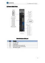
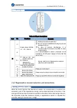
2.6 CN2 Encoder
Please ground both driver and motor PE terminals to avoid any servo alarms.
It is recommended to use a shielded twisted pair cable not longer than 20m.
Please leave a space of min. 30cm between motor power cable and encoder to avoid
interference.
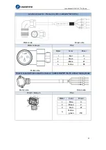
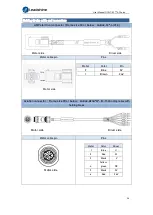
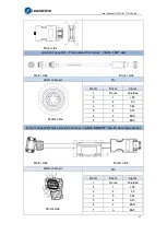
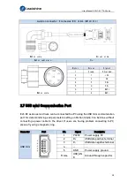
Motor encoder cable selection
AMP electrical connector (Frame size 80 or below
)
CABLE-7BM*-Z(V3.0)
Motor side Driver side
Motor cable pin
Pins
Motor side
Motor
Driver
Signal
1
Frame
Shielded
2
1
+5V
3
2
0V
4
5
SD+
5
6
SD-
6
3
BAT+
7
4
BAT-
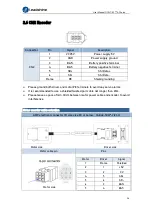
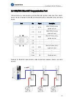
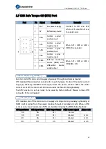
Connector
Pin
Signal
Description
CN2
1
VCC5V
Power supply 5V
2
GND
Power supply ground
3
BAT+
Battery positive terminal
4
BAT-
Battery negative terminal
5
SD+
SSI Data+
6
SD-
SSI Data-
Frame
PE
Shield grounding

