


8. STATUS DISPLAY
159
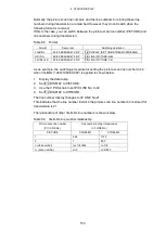
Table 8-7 Reference signal
Input signal
Reference signal
SD, HD, 3G
A
ch
HD (DL)
Link A
3G (DL)-2K, 3G (DL)-4K, 3G (QL), HD (QL)
Link 1
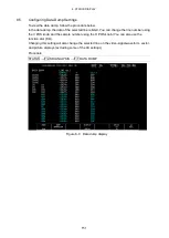
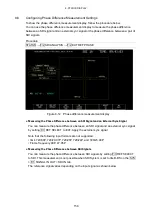
8.6.1
Phase Difference Measurement Display Explanation
●
CURRENT PHASE
V PHASE:
The phase difference is displayed in units of lines.
H PHASE:
The phase difference is displayed in units of time and in units of
pixels or dots. (*1)
TOTAL PHASE:
The total of the V PHASE and H PHASE differences is displayed
here in units of time.
*1 When the input signal is HD (DL) 1080/60P, 1080/59.94P, 1080/50P, or SD, the unit will be dots.
Pixels are in units of the video's sampling frequency. Dots are in units of the parallel video's
transmission clock frequency.
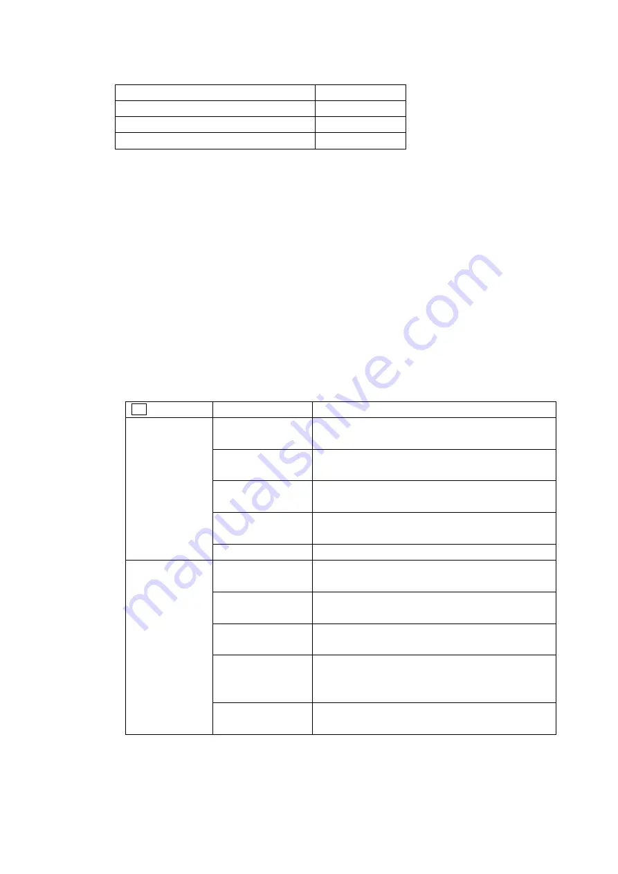
●
REF
This displays the reference signal as shown below.
Table 8-8 REF indications
F•3 REF SELECT
Display Indication
Description
EXT
EXT BB : DEFAULT
Indicates that the external sync signal is BB and the
phase difference is the default value.
EXT BB : USER REF Indicates that the external sync signal is BB and a
user-defined reference is being used.
EXT HD : DEFAULT
Indicates that the external sync signal is an HD tri-level
sync signal and the phase difference is the default value.
EXT HD : USER REF Indicates that the external sync signal is an HD tri-level
sync signal and a user-defined reference is being used.
NO SIGNAL
Indicates that no external sync signal is being applied.
SDI
SDI 1A
Indicates that the input signal is SD, HD, or 3G and the
reference signal is 1A
SDI 2A
Indicates that the input signal is SD, HD, or 3G and the
reference signal is 2A
LINK A
Indicates that the input signal is HD (DL) and the
reference signal is link A
LINK 1
Indicates that the input signal is 3G (DL)-2K, 3G
(DL)-4K, 3G (QL), or HD (QL) and the reference signal is
link 1
NO SIGNAL
Indicates that the reference SDI signal is not being
received.
Содержание LV 5480
Страница 15: ...2 VIDEO SIGNAL WAVEFORM DISPLAY 7 SCALE UNIT HDV SDV SCALE UNIT HD SD SCALE UNIT 150 ...
Страница 38: ...2 VIDEO SIGNAL WAVEFORM DISPLAY 30 COLOR MATRIX XYZ COLOR MATRIX GBR COLOR MATRIX RGB ...
Страница 98: ...5 PICTURE DISPLAY 90 STATUS INFO ON Figure 5 34 Turning the information on and off ...
Страница 119: ...7 AUDIO DISPLAY 111 DISPLAY MODE METER DISPLAY MODE SURROUND DISPLAY MODE STATUS Figure 7 8 Selecting the display mode ...
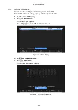
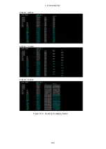
Страница 163: ...8 STATUS DISPLAY 155 DISPLAY SERIAL DISPLAY COMPO DISPLAY BINARY Figure 8 10 Selecting the display format ...
Страница 202: ...9 EYE PATTERN DISPLAY SER02 SER09 194 SWEEP 2UI SWEEP 16UI Figure 9 9 Selecting the sweep time ...