11. VIDEO SIGNAL WAVEFORM DISPLAY
122
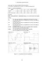
11.6.4
Setting Which Channels to Display
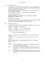
To turn individual channels in a YC
B
C
R
, GBR, or RGB signal on and off, follow the
procedure below.
You cannot set every channel to OFF.
This setting is available when F•1 COLOR MATRIX is set to YCbCr, GBR, or RGB.
However, it is not available when F•2 YGBR or F•2 YRGB is set to ON.
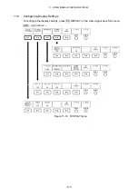
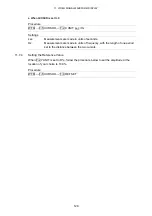
Procedure
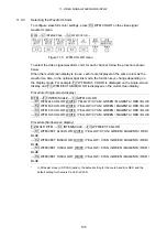
WFM
→
F•4 DISPLAY
→
F•2 SIGNAL DISPLAY
→
F•1 CH1 Y / F•2 CH2 Cb / F•3 CH3 Cr
→
F•1 CH1 G / F•2 CH2 B / F•3 CH3 R
→
F•1 CH1 R / F•2 CH2 G / F•3 CH3 B
Settings
ON:
The specified channel in the YC
B
C
R
, GBR, or RGB signal is displayed (this is
the default value).
OFF:
The specified channel in the YC
B
C
R
, GBR, or RGB signal is not displayed.
11.6.5
Selecting the Filter
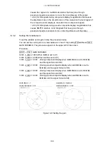
To select the filter, follow the procedure below.
The filters that you can select vary depending on the F•1 COLOR MATRIX setting.
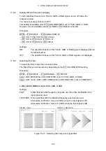
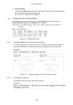
Procedure
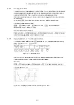
WFM
→
F•4 DISPLAY
→
F•3 ARRANGE
→
F•1 FILTER:
FLAT / LOW PASS (When COLOR MATRIX is set to YCbCr, GBR, or RGB.)
FLAT / LUM / FLAT+LUM / LUM+CRMA (When COLOR MATRIX is set to COMPOSIT.)
●
When COLOR MATRIX Is Set to YCbCr, GBR, or RGB
Settings
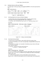
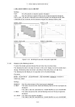
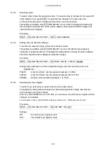
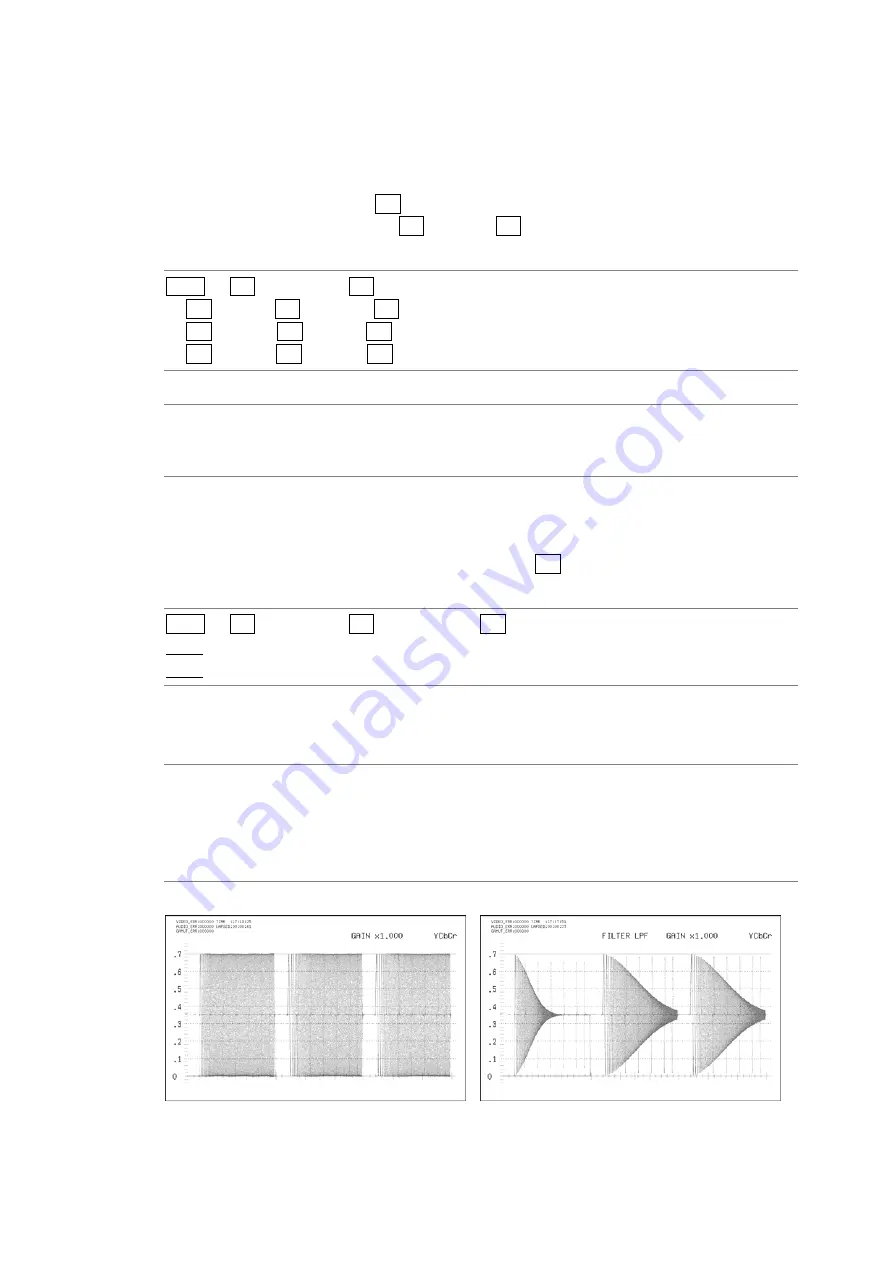
FLAT:
A filter that has a flat frequency response over the entire bandwidth of the
input signal is used.
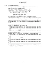
LOW PASS: A low-pass filter with the following frequency responses is used.
Attenuation of 20 dB or more at 20 MHz when the input signal is HD
Attenuation of 20 dB or more at 3.8 MHz when the input signal is SD
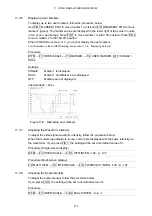
FILTER = FLAT
FILTER = LOW PASS
Figure 11-23 Selecting the component signal filter


