General Repair Practices 37
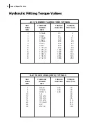
Use correct torque values when reassembling and installing components (see TORQUE
SPECIFICATION CHARTS).
Always check the hydraulic fluid in the hydraulic tank after performing any service or repair of the
hydraulic system.
Always lubricate components with grease fittings after they have been repaired and reinstalled.
Use only Leach/Labrie replacement parts.
N
OTE
:
See Chapter 8
Service and Repair
for specific repair instructions.
Electrical Testing
The electrical system used on the unit consists of various
lights, switches and wiring. Testing the
components and wiring can be accomplished by two simple checks:
checking for voltage
and
checking continuity
.
Diode testing
can also be carried out to check serviceability of diodes.
Checking for Voltage
A test light is used to check for the presence of electricity
in a live circuit. Connect the test light clip to
a good ground and the probe at the point where the presence of voltage is to be checked. If voltage is
present, the light
will be on. If no voltage is present, the light will be off.
Checking Continuity
A continuity tester is used to check the ability of a conductor
to allow current to pass. A continuity
tester uses a self-contained power source and should never be used on a live circuit. Connect the clip
to one side of the component to be tested and touch the probe to the other side. If the component has
the potential to pass current, has continuity, the light will be on. If the component is not able to pass
current, there is no continuity and the
light will be off.
Diode Testing
A diode is a
one way electrical “check valve”, that will only allow electrical power to pass in one
direction.
This is used when multiple circuits are connected together with a single point of contact,
either power or ground, to allow each circuit to act independently without supplying power to other
circuits.
To test a diode or diode pack, a digital multimeter with a resistance and/or a diode test setting is
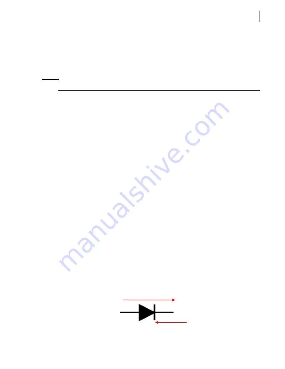
required. To test a diode we must first understand the power’s path of flow within the diode. The
diode symbol on wiring schematics is:
Power Flow
Allowed to Pass
X
Power Flow
Blocked
Anode
Cathode
Содержание 2R-III
Страница 1: ...2R III MAINTENANCE MANUAL...
Страница 2: ......
Страница 3: ...2R III MAINTENANCE MANUAL...
Страница 5: ......
Страница 6: ......
Страница 20: ...10 Introduction...
Страница 42: ...32 Safety...
Страница 58: ...48 Preventive Maintenance Figure 5 1 Hydraulic tank w return filter 1 2 3 4 5 6 7 8...
Страница 66: ...56 Preventive Maintenance...
Страница 102: ...92 Troubleshooting...


