


7
The tuner shield is a fairly tight fit, so you may have to gently flex the sides of the Jupiter chassis
to slide the tuner in. Align the four mounting holes in the tuner shield with the four holes in the
Jupiter chassis. Secure with the four small cross-point screws provided. Hand tighten only; do not
overtighten.
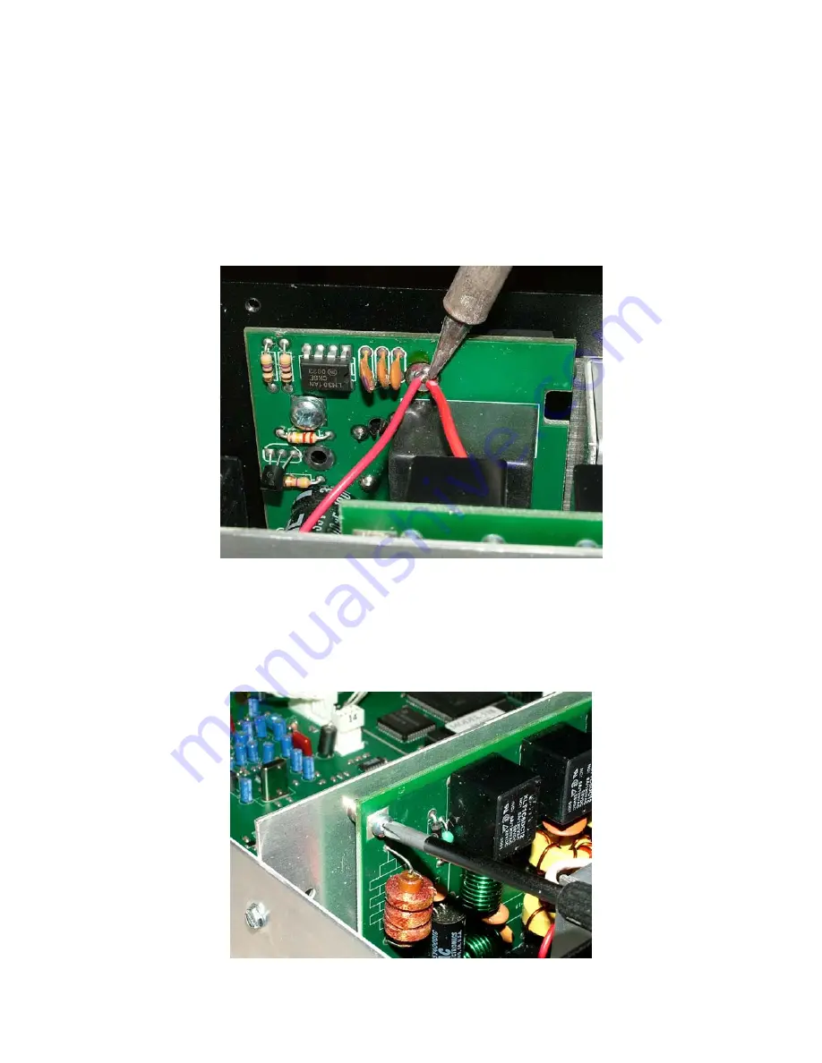
Step 4: Route the red wire from the JT-11 to the vertical board on the inside-back of the radio,
just to the left of the RF deck. Locate the top-center solder pad that already has one red wire
soldered to it. Carefully tack solder the red wire from the JT-11 to this same solder pad. When
you're done, there should be two red wires soldered to this pad.
Step 5: Locate the FILTER board. It is the vertically mounted board behind the DSP/LOGIC
board, between it and the RF deck. You will loosen, but not remove this board.
Step 6: Using a medium Phillips screwdriver, remove the four screws holding the FILTER board
to the vertical chassis wall. This will allow you to move the board enough to complete the next
few steps.