
29
The LDG AT-200PC
In 1995 LDG pioneered a new type of automatic antenna tuner. The LDG design uses banks of
fixed capacitors and inductors, switched in and out of the circuit by relays under microprocessor
control. A built-in SWR sensor provides feedback; the microprocessor searches the capacitor and
inductor banks, seeking the lowest possible SWR. The tuner is a “Switched L” network consisting
of series inductors and parallel capacitors. LDG chose the L network for its minimum number of
parts and its ability to tune unbalanced loads, such as coax-fed dipoles, verticals, Yagis; in fact,
virtually any coax-fed antenna. The inductors are switched in and out of the circuit by relays
controlled by the microprocessor. An additional relay switches between high and low impedance
ranges.
The capacitors are connected to ground with the seven inductor relays. Another relay switches the
entire capacitor bank to the input or output side of the inductor. This switching allows the AT-
200PC to automatically handle loads that are greater than 50 ohms (high setting) and less than 50
(low setting). All of the relays are sized to handle over 300 watts continuously.
The SWR sensor is a variation of the Bruene circuit. This SWR measuring technique is used in
most dual-meter and direct-reading SWR meters. Slight modifications were made to the circuit to
provide voltages (instead of currents) for the analog-to-digital converters (ADCs) that provide
signals proportional to the forward and reverse power levels. The single-lead primary through the
center of the sensor transformer provides RF current sampling. Diodes rectify the sample and
provide a dc voltage proportional to RF power. Variable resistors calibrate the FORWARD and
REVERSE power levels. Once adjusted, the forward and reverse power sensors produce a
calibrated DC voltage proportional to the forward and reverse RF power levels. These two
voltages are read by the ADCs in the microprocessor. Once in a digital format, the they are used
to calculate SWR in real time.
Although the microprocessor’s oscillator runs at 20 MHz. The main tuning routine takes about 75
cycles to make a tuner adjustment and take a new SWR measurement, or 7 milliseconds per tuner
adjustment. If running at maximum speed, the microprocessor can try all inductor-capacitor
combinations in under 3 seconds. Unfortunately, the mechanical relays can’t react as quickly as
the microprocessor, and the tuning speed must be slowed down to compensate for relay settling
time.
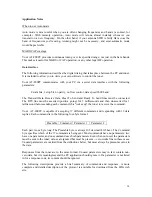
The tuning routine, written in assembly language, uses an algorithm to minimize the number of
tuner adjustments. The routine first de-energizes the high/low impedance relay if necessary, then
individually steps through the inductors to find a coarse match. With the best inductor selected,
the tuner then steps through the individual capacitors to find the best coarse match. If no match is
found, the routine repeats the coarse tuning with the high/low impedance relay energized. The
routine then fine tunes the capacitors and inductors. The program checks LC combination to see if
a 1.5 or lower SWR can be obtained, and stops when it finds a good match.
The microprocessor runs a fine tune routine just after the tuner finds a match at an SWR of 1.5 or
less. This routine tries to get the SWR as low as possible (not just 1.5); it takes about a half
second to run. There is also a quick tune mode. If the swr is below 2.0 when you press the tune
button to start a tuning cycle, the tuner will first try a memory tune routine to see if it can achieve
a low swr without a complete re-tune. This also takes about a half second to run. If it does not
find a good match, then it runs a full tuning routine.