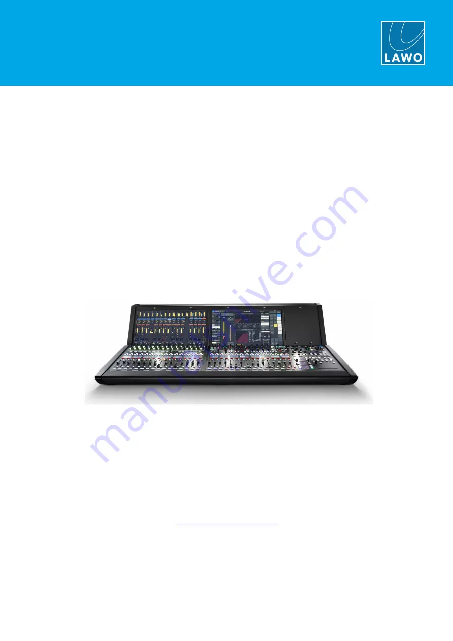
mc²36 xp
Installation & Service Guide
Version: 1.0/1
To obtain the latest documentation and software downloads, please visit:
Edition: 16 August 2023
www.lawo.com/lawo-downloads
Страница 1: ...mc 36 xp Installation Service Guide Version 1 0 1 To obtain the latest documentation and software downloads please visit Edition 16 August 2023 www lawo com lawo downloads...
Страница 2: ...ers It cannot be guaranteed that all product names products trademarks requisitions regulations guidelines specifications and norms are free from trade mark rights of third parties All entries in this...
Страница 3: ...Installation Service Guide Version 1 0 1 Table of Contents 1 About this Documentation 4 2 Important Safety Instructions 5 3 Important Cleaning Instructions 6 4 The Hardware 7 5 Installation 25 6 Servi...
Страница 4: ...cal drawings and data sheets including weights and dimensions are available from the Lawo Download Center after login We also recommend that you carefully observe the release notes for your product sy...
Страница 5: ...mponents please read and observe all of the instructions provided in the General Safety Information for Lawo Equipment booklet delivered with your devices Double click here to open the same informatio...
Страница 6: ...d the lifespan can be dramatically shortened Please note that some substances can lead to discoloration of surfaces Lawo is not responsible for damage caused by the unauthorized use of disinfectants o...
Страница 7: ...re This chapter describes the control surface frame and its hardware components Introduction Centre Section 16F Controls Channel Controls for 32F 48F Mounting Options Overbridge Options Frame Variants...
Страница 8: ...ature controlled and so under normal operating conditions they are inactive Key Facts Frame size layout 16 32 or 48 faders Frame width mounting version either Studio or OB van Dual redundant AC power...
Страница 9: ...control connection to the Core is established the audio parts of the system will start to function the DSP channels and routing matrix This connection can be made using either in band or out of band c...
Страница 10: ...resolution touch screen TFT display 1 x Blanking Panel OVB 976 15 A full height blanking panel for the overbridge 1 x Central Panel 976 20 with 16 x 100mm motorised faders touch sensitive 43 x rotary...
Страница 11: ...the left of the centre section The dual fader panel provides a second row of short scale fader strips at the expense of the rotary controls and FC Preset Bank Layer ISO Bay buttons The single and dual...
Страница 12: ...strips 1 x Channel Display 977 13 A high resolution touch screen TFT display identical to the one in the centre section 1 x Double Fader Panel 976 11 with 16 x 60mm motorised faders touch sensitive 1...
Страница 13: ...OB van mobile mounting Studio Live Version OB Truck Version The Studio version comes with wider side panels and is ready for table top mounting The OB van version is fitted with narrow aluminum side p...
Страница 14: ...Version 1 0 1 14 59 4 The Hardware 4 6 Overbridge Options The space to the right of the Central GUI is fitted with a full height blanking panel 976 15 This provides a general utility space to mount o...
Страница 15: ...0 Weight 37 kg 81 6 lbs 32 fader Studio 976 32S_xp Dimensions 1343 x 820 x 380 mm 52 9 x 32 3 x 15 0 Weight 54 kg 119 1 lbs 32 fader OB van 976 32V_xp Dimensions 1275 x 820 x 380 mm 50 2 x 32 3 x 15...
Страница 16: ...lifted on or off for removal 2 Ventilation Holes Sticker The sticker shows the direction of airflow required for convection cooling and the minimum distance requirements for installing the frame 3 MA...
Страница 17: ...n off switch and so it is recommended that you install a master power switch to control all of the power supplied to the frame The status of each PSU can be monitored from the Central GUI If you need...
Страница 18: ...ith connector for Australia IEC Lock JPN 436 7219 000 Power Cord with connector for Japan Using the AC Supplies Before connecting power to the frame please read and observe all of the instructions in...
Страница 19: ...d observe all of the instructions in the General Safety Information for Lawo Equipment booklet delivered with your devices The control surface must be on the same potential as all other system devices...
Страница 20: ...le 8 x AES3 IN wired to 8 x XLR female 8 x AES3 OUT wired to 8 x XLR male 1 x 64 channel MADI available via SFP see below 8 x GPIO wired to 1 x 37 pin D type female For more information see Connector...
Страница 21: ...rface provides RAVENNA multi channel digital audio over IP Up to 256 bi directional channels at 48kHz AND 96kHz Up to 128 TX and 128 RX streams RAVENNA provides full SMPTE ST2110 30 and AES67 compatib...
Страница 22: ...nels and displays connect to an Ethernet server mounted inside the frame either a Bayserver in channel bays or Gateserver in the centre section The connections are made using both USB and Display Port...
Страница 23: ...A rear panel wired from the Local I O RAVENNA AES67 interface How to use each port is described later see Wiring Additional Notes for the Gateserver The Gateserver provides a sophisticated computing...
Страница 24: ...at it may be removed when not required Please note that there is no locking mechanism to anchor the script tray to the console and so it must be removed for transportation When fitted the tray glides...
Страница 25: ...uide Version 1 0 1 25 59 5 Installation 5 Installation This chapter describes how to install the control surface Installation Instructions Unpacking Installing the Frame Installing the Console Keyboar...
Страница 26: ...ructions BEFORE installing or servicing any component Once you are ready to begin it is recommended to complete the tasks in the following order Unpack Install the Frame Install the Console Keyboard F...
Страница 27: ...on the component s ordered Included The following items are included with each control surface 2 x 2m IEC power cables country specific to connect mains power to the frame 1 x USB keyboard to be inst...
Страница 28: ...ound the device for cooling Dimensions and Weight The dimensions and weight vary depending on the frame variant Mechanical drawings and data sheets for all frame variants are available from the Lawo D...
Страница 29: ...mc 36 xp Installation Service Guide Version 1 0 1 29 59 5 Installation Minimum Distances for Control Surface Mounting 5 3 1 Studio Frame OB Van Frame...
Страница 30: ...on top of the control surface when it is needed Usually it is connected to one of the USB ports on the front buffer below the centre section arm rest A suitable cable is provided The keyboard is avai...
Страница 31: ...l components When fitting an optical transceiver you must use the correct fiber type for your remote device Using the wrong fiber type or exceeding the maximum optical input power can result in a malf...
Страница 32: ...r removal SFP modules must only be removed when there is no cable connected 1 Disconnect the cable from the SFP module We recommend that you label the cable before it is disconnected for easy reconnec...
Страница 33: ...I O streaming AND in band control both non redundant MGMT ports to the management network for out of band control can be redundant AND MISC A to the media network for local I O streaming non redundan...
Страница 34: ...ork Port 1 x 1GbE The MISC A port provides a connection to the RAVENNA AES67 interface of the Local I O It is used to stream the local I O signals to and from the Core via the media network It can als...
Страница 35: ...e Central Panel 976 20 can be used to connect a talkback microphone It is wired directly to the male XLR marked TB on the console s rear panel Note that the console does not include a dedicated talkba...
Страница 36: ...vice procedures available for the control surface hardware Using the Service Procedures Restarting a Bayserver or Gateserver Replacing a Panel Using the Hood Fastener Replacing a Fader Replacing a TFT...
Страница 37: ...rocedures The workspace must be ESD proof Before removing parts of the casing shields etc the device MUST be switched off and disconnected from the mains supply Check the unit for electrical safety af...
Страница 38: ...le You should perform this procedure if the graphics on an individual display freeze or look odd Or if the controls and indicators on a panel do not respond or update These symptoms can sometimes occu...
Страница 39: ...s DO NOT attempt to open the frame without first disconnecting the mains supply 1 Remove the screws at the bottom of the panel using a T20 Torx driver The number of screws vary depending on the panel...
Страница 40: ...connectors for the panel s Talkback XLR and USB port 5 Carefully remove the panel by lifting it out of the frame Lay it it face down on a piece of foam or similar ESD proof protective material away fr...
Страница 41: ...the frame without first disconnecting the mains supply 1 Follow the previous section s steps to lift the panel You will see the Hood Fastener stowed safely within the frame 2 Release the fastener fro...
Страница 42: ...pen the frame without first disconnecting the mains supply 1 Remove the panel from the console frame as described earlier and lay it it face down on a piece of foam or similar ESD proof protective mat...
Страница 43: ...it helps to support it from behind as you turn the panel You are now ready to fit the replacement 7 Insert the new fader unit into position 8 Carefully lift the panel onto its side supporting the fade...
Страница 44: ...e long enough to turn the countersunk screws without scratching the front panel If you attempt to use a short driver or driver attachment damage can occur 2 Remove the connectors taking note of where...
Страница 45: ...a PSU block is installed in the bay S1 DIP Switch 4 GUI Mode sets the GUI mode ON Central GUI OFF Channel Display S1 DIP Switch 3 5 6 7 8 are unused and should be set to OFF SW1 Rotary Switch Address...
Страница 46: ...n place using the Hood Fastener As soon as you lift the panel you will see the server mounted inside the frame Note that you do not need to disconnect any cables The function of the connectors and swi...
Страница 47: ...ase the plug You must remove the MAINS connectors from the frame rather than from the wall as the IEC sockets form part of the PSU module If you do not then the PSU module will get stuck during step 8...
Страница 48: ...to drop any nuts or washers into the desk 8 Remove the PSU block from the frame 9 Now fit the replacement and secure using the five hex nuts shown in step 7 10 Replace the power signal and grounding...
Страница 49: ...ling from the rear panel and remove the Central Panel Central GUI display and Overbridge blanking panel DO NOT attempt to open the frame without first disconnecting the mains supply 1 Disconnect all o...
Страница 50: ...ree on each side holding the unit in place Remove all of the screws using a T20 Torx driver 5 Carefully remove the unit by sliding it out of the rear of the console frame Take care that the frame does...
Страница 51: ...the internal connectors from the front of the unit taking note of where each one should be fitted There are several RJ45 network connectors on the left plus a single power connector on the right 3 No...
Страница 52: ...mc 36 xp Installation Service Guide Version 1 0 1 52 59 6 Service Procedures 7 Restart the Gateserver to refresh the communication with the control system...
Страница 53: ...ion Service Guide Version 1 0 1 53 59 7 Appendices 7 Appendices This chapter includes further information which you may find useful Part Numbers Mechanical Drawings Wiring Diagrams Connector Pin Outs...
Страница 54: ...Van Side Panels 976 61 Control Surface Modules Fader FC Panel 976 32 only 976 10 Double Fader Panel 976 48 only 976 11 Central Panel 976 20 Channel Display 977 13 Overbridge Blanking Panel 976 15 Inte...
Страница 55: ...5 59 7 Appendices 7 2 Mechanical Drawings The following diagrams show the mechanics of each control surface variant In each case double click on a link to open the diagram as a pdf 16 Fader OB Van 16...
Страница 56: ...ce Guide Version 1 0 1 56 59 7 Appendices 7 3 Wiring Diagrams The following diagrams show the control surface internal wiring in more detail In each case double click on a link to open the diagram as...
Страница 57: ...r a high pass filter and 20dB PAD The maximum analog input level with the PAD enabled is 24dBu Talkback TB 7 4 2 3 pin XLR connector male This connector is wired from the 3 pin female XLR Talkback con...
Страница 58: ...Appendices AES3 In 7 4 4 3 pin XLR connector female All AES3 IN connections conform to the stereo AES3 standard The inputs have sample rate conversion SRC AES3 Out 7 4 5 3 pin XLR connector male All...
Страница 59: ...mc 36 xp Installation Service Guide Version 1 0 1 59 59 7 Appendices GPIO 7 4 6 37 pin D type connector DB37 female Headphones 7 4 7 6 35mm stereo jack connector...