background image

A__madi4 User Guide

Version: 10.0.0/4

8/68

4. Controls, Connectors & Indicators

 6 

  Power (PSU 1 & 2)

The  unit  is  fitted  with  two  independent  power  supplies  running  in  parallel.  Only  one  supply  is  required  for
operation.  For  redundancy,  connect  both  supplies,  each  to  a  separate  AC  mains  circuit.  The  PSU  LEDs  on  the
front panel show the status of each supply. 

The 

CASE

 grounding screw should be used to ground the frame.

For power consumption and electrical voltages, please refer to the 

A__madi4 

Data Sheet.

All devices 

MUST

 be connected to the mains using the three-cord power leads supplied with the system.

When running with two mains supplies (PSU 1 and PSU 2), make sure that both circuits lie on the same
ground potential. Otherwise, an internal bridge of two ground wires will lead to a ground loop!

 7 

  Ventilation Holes (Cooling)

The  unit  is  fitted  with  a  single  speed-controlled  fan.  Air  is  sucked  in  from  the  rear  panel,  and  blown  out  at  the
sides (left and right).

DO NOT

 obstruct the ventilation holes as to do so will prevent efficient cooling.

4.1

The NET-ID Button

The NET ID button and LED on the  front  panel  can  be  used  to  reset  the  service  network  IP  address  or  perform  a
factory reset. For safety reasons, a press and hold is required; a quick press of the button performs no action.

Resetting the Service Network IP Address

This operation will reset the service network IP address to its default = 

192.168.110.253

.

First, make sure that the interface is  booted  and  operating  normally  -  the 

NET ID

 LED  should  be  blinking  yellow.

Then,  using  a  pointed  object,  press  and  hold  the  recessed  button  until  the  LED  lights  continuously.  When  the
LED switches off, the reset is complete.

Performing a Factory Reset

While the unit is booting, you can press and hold  the 

NET ID

 button to perform a factory reset.  This  operation  will

delete all configuration files AND reset the service network IP address. 

First power cycle the unit to start a reboot. Then press and hold the

 NET ID

 button, while the LED blinks red,  until

the LED lights continuously - this indicates that the reset is taking place. When the LED switches off, the reset  is
complete.

Note  that  when  the  unit  restarts,  there  will  no  conversion  mode  (indicated  by  the  fast  blinking  orange  MADI  port
LEDs). Therefore, the next step must be to 

select

 the conversion mode for each BRIDGE.

Содержание A_madi4

Страница 1: ...A__madi4 User Guide Version 10 0 0 4 To obtain the latest documentation and software downloads please visit www lawo com downloads Edition Wednesday April 17 2019...

Страница 2: ...ers It cannot be guaranteed that all product names products trademarks requisitions regulations guidelines specifications and norms are free from trade mark rights of third parties All entries in this...

Страница 3: ...Instructions 5 3 Overview 6 4 Controls Connectors Indicators 7 5 The Conversion Modes 9 6 The RAVENNA Ports 11 7 Synchronization 15 8 Installing the Unit 18 9 Connecting a Service Computer 21 10 The L...

Страница 4: ...ements and suitable components for AoIP All Lawo manuals are available from the Downloads area at www lawo com after Login Look out for the following which indicate Notes points of clarification Tips...

Страница 5: ...tant Safety Instructions 2 Important Safety Instructions Please observe all of the instructions provided in the General Safety Information for Lawo Equipment booklet delivered with your devices Double...

Страница 6: ...nversion modes RAVENNA Link to from MADI DALLIS this mode converts Lawo s RAVENNA Link to MADI both audio and control are converted The mode is designed to connect an existing DALLIS with MADI master...

Страница 7: ...r port is accompanied by two status LEDs Active LED yellow data transmission off no data transmission Link LED green link established off no link 4 MADI 1 2 Each BRIDGE module provides two MADI ports...

Страница 8: ...The NET ID button and LED on the front panel can be used to reset the service network IP address or perform a factory reset For safety reasons a press and hold is required a quick press of the button...

Страница 9: ...ote that the inverse use e g connecting a DALLIS with RAVENNA Link master board to a MADI IO Module is not technically possible The connection must be made to the ETHERNET A port on the A__madi4 ETHER...

Страница 10: ...z 88 2kHz 96kHz At sample rates of 88 2kHz and 96kHz the number of MADI channels are halved The clock is always taken from the RAVENNA Link port 5 3 RAVENNA to from MADI raw This mode converts RAVENNA...

Страница 11: ...k equipment between RAVENNA Link connections 6 2 RAVENNA Net All RAVENNA Net interfaces provide SMPTE 2110 30 31 AES67 RAVENNA multi channel digital audio over IP Per port up to 128 bi directional cha...

Страница 12: ...re ports please fit one of the Lawo certified SFP Modules Note that the SFPs must be Lawo certified Options include mulit mode and single mode fibre supporting a choice of maximum cable lengths If Bot...

Страница 13: ...10 0 0 x onwards Concept The diagram below illustrates the concept in a standard data network A SMPTE 2022 7 enabled transmitter duplicates the input stream and sends it via two different paths to th...

Страница 14: ...RAVENNA Web UI they appear as ra0 and ra1 This is important to know when editing settings for the RAVENNA Net streaming ports using the Web UI Front Connector Panel Network Interfaces in the Web UI Cr...

Страница 15: ...ule PTP arriving from sending to the RAVENNA streaming network via ETHERNET A or ETHERNET B Internal the device s own internal sync generator To sync to an external reference the clocking signal MUST...

Страница 16: ...etworks red and blue This brings a number of advantages A__madi4 can transmit PTP to the network via both of its interfaces Thus supporting the two separate network paths required for SPS A__madi4 pro...

Страница 17: ...reliable Wordclock signal that can be distributed to all nodes on the network Please note For correct synchronization without PTP the same sync source must be selected at all streaming nodes All nodes...

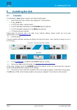
Страница 18: ...awo representative or email support lawo com 2 Install the frame The unit is delivered with rack mounting ears fitted to the sides of the frame this is ideal for mounting the unit in a 19 housing Fron...

Страница 19: ...more details please refer to the SFP module s data sheet SFP Module Description Part Number 1000 BASE SX 850nm 7dBm multi mode fibre 550m 981 60 10 1000 BASE LX 1310nm 3dBm single mode fibre 10km 981...

Страница 20: ...dress of each streaming port IMPORTANT Each streaming port must be given a unique IP address before it is connected to the network to avoid IP conflicts 3 Connect BRIDGE 1 to its partnering device RAV...

Страница 21: ...he port you are connecting to In all Lawo systems the default Subnet Mask 255 255 255 0 Default Gateway A Default Gateway setting is required if data packets are to be redirected For example if the PC...

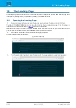
Страница 22: ...field The default 192 168 110 253 but this can be edited from the Device configuration page If the IP address is unknown then it can be reset using the NET ID button on the front panel Note that ther...

Страница 23: ...s resource is hidden And in service mode Configuration Backup and Restore backup and restore options for use when exchanging a unit Service Support can be used to download a snapshot of the settings u...

Страница 24: ...the Open RAVENNA Butler option will be greyed out if either there is no interface mode or the mode is converting to from RAVENNA Link Configuration Tasks 1 First check and if necessary update the sof...

Страница 25: ...is not required when converting to from RAVENNA Link 11 5 Software The current version is shown in the Software area Please check this against the latest release available from the Downloads area at w...

Страница 26: ...nd restored using the Backup Restore Config tool This is ideal if you need to exchange a device 12 2 Prerequisites To run the RAVENNA Web UI your computer MUST meet or exceed the following requirement...

Страница 27: ...e Home page A pop up window appears 2 Type in the Password ravenna and click OK The Home page updates to show all of the locked functions and Enable Edit Mode updates to Expert Settings to access to t...

Страница 28: ...he RAVENNA release Click on Other RAVENNA Devices to navigate to another device s Home page 2 Device ID and other details This area defines the Device ID For the A__madi4 the Device ID can be edited b...

Страница 29: ...urce What you see will vary slightly depending on the device s PTP mode master slave or slave only Master Slave device running as PTP Master Beside ID you will see the MAC address of the device Hover...

Страница 30: ...cribed in more detail later Click on Create to create a new TX stream Click on an existing stream name to interrogate or edit its configuration Click on SEL ALL to select all TX streams Or click on an...

Страница 31: ...ick on Other network settings to view the general settings applied to all ports 2 Use the fields to type in a value or select a menu option 3 If you make a change select Apply to confirm or Cancel 4 T...

Страница 32: ...y the ra1 ETHERNET B interface defaults to off Therefore to activate the interface you will need to enter a suitable IP address The Network Mask must match the Subnet Mask of all other RAVENNA streami...

Страница 33: ...all other streaming nodes determine the current PTP master Prio1 and Prio2 PTP uses a master slave approach in which all master capable devices elect the best master called the grandmaster according...

Страница 34: ...ll of the media s sending TX streams If the media has already been assigned to an active TX or RX stream then it will be locked as shown below 2 To unlock a media first close the window and use the To...

Страница 35: ...f the following options WCLK In external wordclock connected to the WCLK IN MADI 1 or MADI 2 connected to the MADI 1 or MADI 2 connectors RA Link connected to the alternate BRIDGE module PTP arriving...

Страница 36: ...ce you have completed all of the settings check the network packet size shown in the box that starts Your configuration results in The network packet size cannot exceed the the Maximum Transmission Un...

Страница 37: ...later by interrogating the TX stream manual the interface is active and you will need to enter your own multicast IP address Choose this option if your network supports a limited IP range To configur...

Страница 38: ...A__madi4 User Guide Version 10 0 0 4 38 68 12 The RAVENNA Web UI The diagram below illustrates how the TX stream properties relate to other parts of the configuration...

Страница 39: ...he digital audio For example L16 16 bit Linear PCM L24 24 bit Linear PCM AM824 24 bit Linear PCM 8 bit metadata a non standard format commonly used in AES EBU Channel count the number of channels to b...

Страница 40: ...stream has been published to the network ra0 and ra1 if you selected auto for either of the RAVENNA interfaces then you will now see the multicast IP address which has been been allocated SDP and URLs...

Страница 41: ...ote that the streams listed in the Connect menu are dependent on the TX streams being announced to the network via their SDP information As this is not always supported by all devices you can open an...

Страница 42: ...a RAVENNA compliant stream Note that it is NOT permitted to assign the same SDP or two non redundant SDPs In these instances an error message will appear and will need to remove the assignment to the...

Страница 43: ...ing must connect to the same 981 61 RAVENNA IO module that is transmitting the PTP signal Request unicast In the current release this option should be left disabled as RAVENNA streaming supports multi...

Страница 44: ...can see the sending node the stream will automatically be displayed in the RX Stream Connect menu If the receiving device does not use mDNS or cannot see the sending device then the automatic listing...

Страница 45: ...lick on the SDP button to copy the stream s SDP information to the clipboard If the stream is redundant then information about both of the paths is contained in the same SDP 3 Now open a Web UI connec...

Страница 46: ...ceiving device paste the clipboard contents into the Stream Source field If the TX stream is redundant copy and paste the URL for the each of the sending interfaces separately enter the ra0 URL into t...

Страница 47: ...m Green correct operation Red there is either no connection or no data Orange the stream is being received but there are drop outs in the data You will also see an icon on the right of each RX stream...

Страница 48: ...ry few seconds on the right is the peak value reached since the last reset Note that the Min Offset should never reach zero as this would mean that the buffer was empty Typically the Min Offset should...

Страница 49: ...ction to the sending device and make sure that the TX Stream Properties are configured to use both RAVENNA interfaces This means assigning a multicast IP address to both of the ra0 and ra1 fields ra1...

Страница 50: ...ly other difference from a non redundant stream is that the Streams entry under Receiver Settings shows two lines one for the main and one for the redundant source By default these are assigned to the...

Страница 51: ...and paste the SDP or RTSP URLs from the sending device Note that the same SDP will announce both streams If you need to use RTSP URLs then take care to copy and paste each one separately enter the ra0...

Страница 52: ...uts are fed from MADI0 while the second 64 outputs are fed from MADI1 Similarly the MADI0 outputs are fed from RAVENNA inputs 1 to 64 and MADI1 outputs from RAVENNA inputs 65 to 128 To change the matr...

Страница 53: ...nd the Recording tracks which increment automatically across the batch of streams The example above shows the set up for four identical RAVENNA Stereo Streams named TEST1 to TEST4 where TEST1 uses Mic...

Страница 54: ...T to select a consecutive range of streams 3 Press and hold CTRL to select non consecutive streams 4 Click on the Select All icon to select or deselect all streams TX Streams Select All active 12 17 U...

Страница 55: ...or RX streams This is recommended if you are using an external control system such as VSM to control the streaming connections Backup and restore config This tool will backup and restore the complete...

Страница 56: ...ttings will be affected are included in the release notes 3 Select Expert Settings Firmware update 4 Select the update file tar gz and then Start Update After a successful update the device will autom...

Страница 57: ...ilable from the Expert Settings menu of the RAVENNA Web UI To create a backup 1 Open the Landing page in service mode select Configuration Backup Restore and then click on the graphical preview The Co...

Страница 58: ...erride all of the device s RAVENNA settings Therefore make sure that you are connected to the correct unit before performing a restore 2 Click on the Browse button select the backup file and then clic...

Страница 59: ...apshot file 1 Open the Landing page in service mode select Service Support and then click on the graphical preview The Service Support page opens in a new browser tab 2 Click on the snapshot sh link y...

Страница 60: ...nges to the MADI port status are not logged Configuring the Syslog Server The entries can be sent in parallel to a syslog server and the configuration is made by opening a telnet session to the device...

Страница 61: ...he Tera Term Pro Telnet client 4 Select TCP IP from the Setup menu and add the IP address of your device to the host list 5 Now open a new Telnet connection using File New connection 6 Choose the TCP...

Страница 62: ...h a parameter manually within the A__madi4 This can be useful when configuring and testing an Ember controlled device To use the application 1 Download the bz2 or xz archive from the location https gi...

Страница 63: ...u have configured the TCP IP settings of your computer s network interface card 2 On a Windows 7 PC type cmd into the Search programs and files field under the Start menu and press Enter This opens th...

Страница 64: ...guration so check the network connections and TCP IP settings again Or contact your network administrator Ping Test Success If the ping test is successful then the result will show that the Sent packe...

Страница 65: ...nfigurable IO device Each DALLIS frame can be fitted with a combination of plug in IO cards DHCP Dynamic Host Configuration Protocol Commonly used in data networks to dynamically allocate IP addresses...

Страница 66: ...supports 254 clients nodes If communication is required outside of the broadcast domain for example to a device with an IP address 192 168 102 xxx then the data packets must be redirected using a net...

Страница 67: ...protocol URL address commonly used in establishing point to point media sessions Sample Rate The speed at which the Processing of the system takes samples respective to values from a continuous analo...

Страница 68: ...ta packets from circulating indefinitely UDP User Datagram Protocol A simple connection less networking protocol which is often used in real time applications due to its low latency UDP is suitable fo...

Отзывы: