8-2
(E)
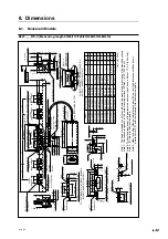
BL57-RE
14 (0.551")
Cable length
1000 (39.370")
4-
ø
2.8 (0.110")
(Mounting hole
for M2.6)
9
(0.354")
14
(0.551")
25
(0.984")
42 (1.654")
60 (2.362")
98 (3.858")
25
(0.984")
15
(0.591")
88 (3.465")
5-
ø
5
(0.197") hole
2
(0.079")
2-M4
×
8
Reference plate
“W
” mounting
screw
5 (0.197")
29
(1.142")
1.5 (0.059")
1.4
(0.055")
5 (0.197")
13.8
(0.543")
16 (0.630")
12 (0.472")
21 (0.827")
0.4
(0.016")
38 (1.496")
25 (0.984")
4 (0.157")
Scale clamp
2-
ø
5
(0.197") hole
25 (0.984")
38 (1.496")
10
(0.394")
Spacer
t = 5 (0.197")
6 (0.236")
2.8
(0.110")
6.3
(0.248")
Stopper (ABS)
Reference plate
“W
”
t = 5 (0.197")
For BL57-006RE
∗
B, 026RE
∗
B, 046RE
∗
B
Reference plate
t = 5
(0.197")
3-
ø
5
(0.197") hole
For BL57-016RE
∗
B, 036RE
∗
B
Unit: mm (inch)
BL57-006RE
∗
B
BL57-016RE
∗
B
BL57-026RE
∗
B
BL57-036RE
∗
B
BL57-046RE
∗
B
60 (2.362")
160 (6.299")
260 (10.236")
360 (14.173")
460 (18.110")
96 (3.780")
196 (7.717")
296 (11.654")
396 (15.591")
496 (19.528")
–
75 (2.953")
120 (4.724")
75 (2.953")
120 (4.724")
2
3
4
5
6
–
2
2
4
4
4
6
8
10
12
Model
Measuring length
L1
L2
–
–
–
75 (2.953")
75 (2.953")
L3
SC
SP
P
1.5 (0.059")
2-M4
×
8
Reference plate mounting screw
Reference plate
2-M4
×
8
Reference plate
“W
” mounting screw
Scale signal detection position
21 (0.827")
16.4
±
0.2
∗
(0.646"
±
0.008"
)
25
±
0.2
∗
(0.984"
±
0.008")
25
±
0.2
∗
(0.984"
±
0.008")
25
±
0.2
∗
(0.984"
±
0.008")
25
±
0.2
∗
(0.984"
±
0.008")
Reference plate
“W
”
SC-
Scale clamp
SP-
Spacer
P-M4
×
8
Scale clamp
mounting screw
Detector head
mounting screw
2-M4
×
12
(
Mounting hole
ø
4.5 (0.177"))
Reference point signal detection position
Scale signal detection position
ø
2.8
(0.110" ) hole
+
0.1 0
+
0.004" 0
6 (0.236")
L2
L2
For BL57-016RE
∗
B, 036RE
∗
B
60 (2.362")
50
±
0.3
∗
(1.969"
±
0.012")
25
±
0.2
∗
(0.984"
±
0.008")
A
0.02 (0.00079")
0.01(0.0039")
0.01(0.0039")
∗
11.4
(0.449")
31
(1.220")
14
(0.551")
22
(0.866")
Reference hole
ø
4
(0.157" )
+
0.05
0
+
0.002" 0
ø
4
(0.157")
50
(1.969")
25
(0.984")
60 (2.362")
42 (1.654")
14 (0.551")
9
(0.354")
Reference
hole
ø
4
(0.157" )
+
0.05 0
+
0.002" 0
25
±
0.2
∗
(0.984"
±
0.008")
25
±
0.2
∗
(0.984"
±
0.008")
L2
L3
98 (3.858")
40
±
0.2
∗
(1.575"
±
0.008")
L1
±
1 (0.039")
88
±
0.3
∗
(3.465"
±
0.012")
1 (0.039")
1 (0.039")
A
M
∗
L2
L3
53.7 (2.114")
17.8
(0.701")
14
(0.551")
8.3 (0.327")
5 (0.197")
44.2
±
0.2
∗
(1.740"
±
0.008")
(4.5)
(0.177")
4.5
(10.177")
9
(0.354")
101 (3.976")
30
(1.181")
40 (1.575")
33
±
0.1
∗
(1.299"
±
0.004")
96
±
0.1
∗
(3.780"
±
0.004")
4.5 (0.177")
36 (1.417")
18
(0.709")
27
±
0.2
∗
(1.063"
±
0.008")
27
(1.063")
2 (0.079")
Reference abutment
surfaces
(Note 5)
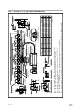
8-2. Soda Lime Glass Models
BL57-
∗∗∗
RE
∗
B (Measuring length 60/160/260/360/460)
Note 1:
The items mar
k
ed b
y an aster
isk indicate the machining dimensions on the mounting surf
ace
.
Note 2:
The surf
ace roughness of the scale mounting surf
ace is Rmax = 6.3 S (250
µ
inch).
Note 3:
The surf
ace roughness of the detector head mounting surf
ace is Rmax = 12.5 S (500
µ
inch).
Note 4:
“M
” ref
ers to the machine guide
.
Note 5:
Mount and adjust the paired ref
erence plate (W) so that their ref
erence surf
aces ha
v
e a
parallelism of 0.01 or less with respect to the machine guide
.
Содержание BL57-RE
Страница 2: ...BL57 RE...
Страница 8: ...6 E BL57 RE...
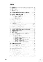
Страница 10: ...ii E BL57 RE 8 Dimensions 8 1 8 1 Neoceram Models 8 1 8 2 Soda Lime Glass Models 8 2 9 Trouble Prevention 9 1...
Страница 14: ...2 2 E BL57 RE...
Страница 28: ...BL57 RE 3 14 E...
Страница 40: ...5 4 E BL57 RE...
Страница 52: ...8 4 E BL57 RE...
Страница 54: ...9 2 E BL57 RE...
Страница 66: ...2 2 G BL57 RE...
Страница 80: ...BL57 RE 3 14 G...
Страница 92: ...5 4 G BL57 RE...
Страница 104: ...8 4 G BL57 RE...
Страница 106: ...9 2 G BL57 RE...

