BL57-RE
3-10
(E)
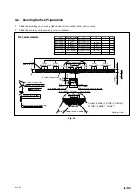
TP7
(AGND)
TP9
(LD)
TP5
(COS)
TP10
(APC)
TP1
(SIN)
TP8
(DGND)
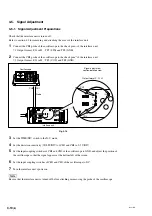
CH1
CH2
Oscilloscope
Signal adjustment
section-detailed view
Probe
TP3
TP2
TP5
TP6
TP901
TP8
CH1
CH2
Output format F, G, H
Interface unit
3-5. Signal Adjustment
3-5-1. Signal Adjustment Preparations
Check that the interface unit is turned off.
Refer to section 4-1 for removing and attaching the cover of the interface unit.
1
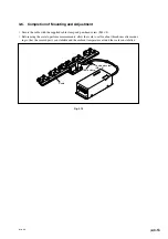
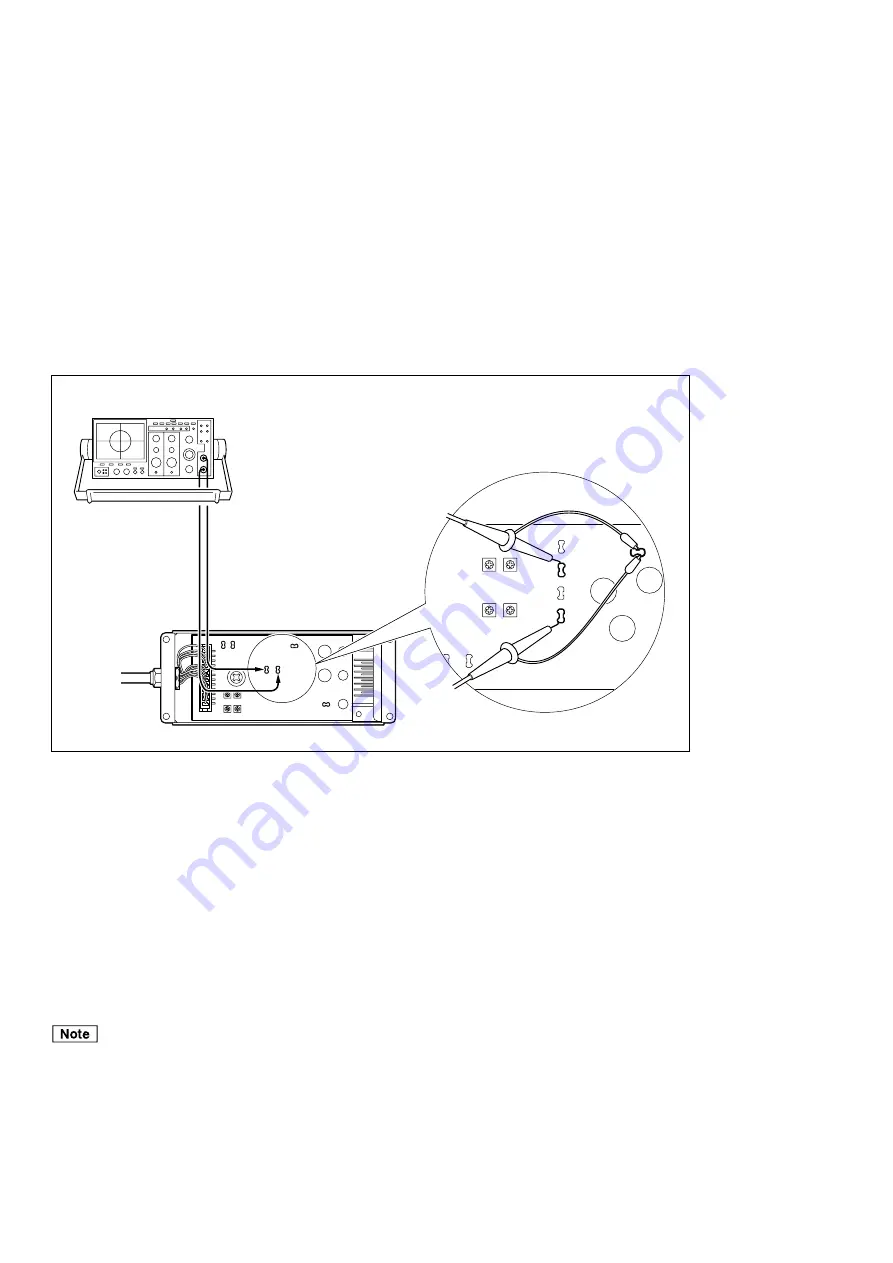
Connect the CH1 probe of the oscilloscope to the check pins
∗
1
of the interface unit.
∗
1 Output format F, G or H : TP3 (SIN) and TP8 (GND)
2
Connect the CH2 probe of the oscilloscope to the check pins
∗
2
of the interface unit.
∗
2 Output format F, G or H : TP2 (COS) and TP8 (GND)
Fig. 3-14
3
Set the TIME/DIV switch to the X-Y mode.
4
Set the deviation sensitivity (VOLTS/DIV) of CH1 and CH2 to 0.5 V/DIV.
5
Set the input coupling switches of CH1 and CH2 of the oscilloscope to GND, and adjust the position of
the oscilloscope so that the signal appears at the bottom left of the screen.
6
Set the input coupling switches of CH1 and CH2 of the oscilloscope to DC.
7
Turn the interface unit’s power on.
Be sure that the interface unit is turned off before attaching or removing the probe of the oscilloscope.
Содержание BL57-RE
Страница 2: ...BL57 RE...
Страница 8: ...6 E BL57 RE...
Страница 10: ...ii E BL57 RE 8 Dimensions 8 1 8 1 Neoceram Models 8 1 8 2 Soda Lime Glass Models 8 2 9 Trouble Prevention 9 1...
Страница 14: ...2 2 E BL57 RE...
Страница 28: ...BL57 RE 3 14 E...
Страница 40: ...5 4 E BL57 RE...
Страница 52: ...8 4 E BL57 RE...
Страница 54: ...9 2 E BL57 RE...
Страница 66: ...2 2 G BL57 RE...
Страница 80: ...BL57 RE 3 14 G...
Страница 92: ...5 4 G BL57 RE...
Страница 104: ...8 4 G BL57 RE...
Страница 106: ...9 2 G BL57 RE...


