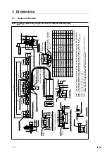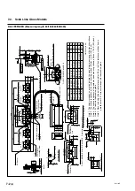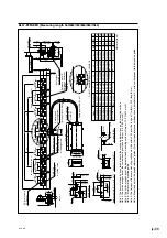
BL57-NE
(E)
7-3
BL57-
∗∗∗
∗∗∗
∗∗∗
∗∗∗
∗∗∗
NE
∗∗∗∗∗
B (Measuring length 560/660/760/860/960/1060)
For BL57-066NE
∗
B, 096NE
∗
B, 106NE
∗
B
L2
L2
33
±
0.1
∗
(1.299"
±
0.004")
L1
±
1 (0.039")
L2
NA
×
L4
L3
L3
L2
NA
×
L4
50
±
0.3
∗
(1.969"
±
0.012")
50 (1.969")
50
±
0.3 (1.969"
±
0.012")
∗
25
±
0.2
∗
(0.984"
±
0.008")
25
±
0.2
∗
(0.984"
±
0.008")
14
25
±
0.2
∗
(0.984"
±
0.008")
25
±
0.2
∗
(0.984"
±
0.008")
25
±
0.2
∗
(0.984"
±
0.008")
25
±
0.2
∗
(0.984"
±
0.008")
25
±
0.2
∗
(0.984"
±
0.008")
25
±
0.2
∗
(0.984"
±
0.008")
25
±
0.2
∗
(0.984"
±
0.008")
Stopper (ABS)
P-M4
×
10
Scale clamp
mounting screw
ø
4
(0.157")
2-
ø
5
(0.197") hole
4-
ø
5
(0.197") hole
50
(1.969")
25
(0.984")
5
(0.197")
Reference plate
“D
”
t = 5 (0.197")
SC-Scale clamp
SP-Spacer
2-Reference plate
“D
”
2-M4
×
10
Reference plate
“D
”
mounting screw
Reference plate
“D
”
Reference abutment
surfaces
(Note 6)
10
(0.394")
4 (0.157")
25 (0.984")
6.3
(0.248")
2.8
(0.110")
6 (0.236")
18
(0.709")
A
0.02 (0.00079")/200 (7.874")
M
Cable length 300 (11.81")
∗
0.1 (0.0039")
1.4
(0.055")
0.4
(0.016")
22
(0.866")
11.4
(0.449
")
14 (0.551")
16 (0.630")
21 (0.827")
4-
ø
2.8 (0.110")
(Mounting hole
for M2.6)
Detector head
mounting screw
2-M2
×
12
(Mounting hole
ø
2.4 (0.094"))
48.7 (1.917")
18.25
(0.719")
14
(0.551")
Scale signal
detection position
21
(0.827")
4.6
(0.181")
40.5
±
0.2
∗
(1.594"
±
0.008")
16.4
±
0.2
∗
(0.646"
±
0.008"
)
31
(1.220")
(3.2)
(0.126")
Spacer t = 5 (0.197")
Scale clamp
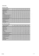
BL57-056NE
∗
B
BL57-066NE
∗
B
BL57-076NE
∗
B
BL57-086NE
∗
B
BL57-096NE
∗
B
BL57-1060NE
∗
B
596 (23.465")
696 (27.402")
796 (31.339")
896 (35.276")
996 (39.213")
1096 (43.150")
560 (22.047")
660 (25.984")
760 (29.921")
860 (33.858")
960 (37.795")
1060 (41.732")
100 (3.937")
75 (2.953")
100 (3.937")
100 (3.937")
75 (2.953")
75 (2.953")
175 (6.890")
225 (8.858")
250 (9.843")
250 (9.843")
300 (11.811")
300 (11.811")
75 (2.953")
75 (2.953")
75 (2.953")
75 (2.953")
75 (2.953")
75 (2.953")
16
18
20
24
26
30
6
7
8
10
11
13
8
9
10
12
13
15
2
3
3
4
5
6
12 (0.472")
38 (1.496")
13.8 (0.543")
25 (0.984")
8 (0.315")
60 (2.362")
9 (0.354")
2 (0.079")
14 (0.551")
38 (1.496")
Unit: mm (inch)
Model
Measuring length
L1
L2
L3
L4
SC
NA
SP
P
A
∗
0.01 (0.00039")
8.3
(0.327")
5
(0.197")
1.5 (0.059")
30
(1.181")
101 (3.976")
96
±
0.1
∗
(3.780"
±
0.004")
40 (1.575")
5 (0.197")
1 (0.039")
1 (0.039")
6
(0.236")
20.5
(0.807")
1.5 (0.059")
13
±
0.2
∗
(0.512"
±
0.008")
ø
2.8
(0.110" ) hole
+
0.1 0
+
0.004" 0
Note 1:
The items mar
k
ed b
y an aster
isk indicate the machining dimensions on the mounting surf
ace
.
Note 2:
The surf
ace roughness of the scale mounting surf
ace is Rmax = 6.3 S (250
µ
inch).
Note 3:
The surf
ace roughness of the detector head mounting surf
ace is Rmax = 12.5 S (500
µ
inch).
Note 4:
“M
” ref
ers to the machine guide
.
Note 5:
The flatness of the scale mounting surf
ace must be within 0.02 o
v
er the r
ange of 7 (width)
×
200 (length) mm.
Note 6:
Mount and adjust the paired ref
erence plates (D) so that their ref
erence surf
aces ha
v
e a par
allelism of 0.1 or less with respect to the machine guide
.
Содержание BL57-003NE Series
Страница 2: ...BL57 NE...
Страница 8: ...6 E BL57 NE...
Страница 10: ...ii E BL57 NE...
Страница 14: ...2 2 E BL57 NE...
Страница 28: ...BL57 NE 3 14 E...
Страница 36: ...4 8 E BL57 NE...
Страница 48: ...7 4 E BL57 NE...
Страница 50: ...8 2 E BL57 NE...
Страница 58: ...ii G BL57 NE...
Страница 62: ...2 2 G BL57 NE...
Страница 76: ...BL57 NE 3 14 G...
Страница 84: ...4 8 G BL57 NE...
Страница 96: ...7 4 G BL57 NE...
Страница 98: ...8 2 G BL57 NE...

