background image


LPMVC-CL025M Manual 

More than Imaging – Laon People


40 

2016-03-04 

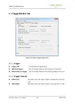
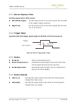
5.10.4.


Overlap Trigger Mode 

In  this  mode,  the  operation  of  the  image  data  transmission  and  the  operation  of  the 
sensor exposure progress simultaneously. In this mode, the maximum frame rate of the 
camera can be used, because it can be used effectively when the frame rate is very fast 
or the exposure time of the sensor is not very short. 


Figure 30. LPMVC-CL025M Overlap Trigger Mode Timing 

Image N 

Image N+1 

Exposure N 

CC1  or  External 
Trigger port 

Exposure 

Image Transfer 

Trigger Width 

Exposure N+1 


Exposure N+2 

Содержание LPMVC-CL025M

Страница 1: ...2016 03 04 LPMVC CL025M User Manual Version 1 0...

Страница 2: ...n 11 3 Camera Specification 12 3 1 Overview 12 3 2 Key Features 13 3 3 Technical Specifications 14 3 4 Sensor Information 15 3 4 1 Sensor Optical Chart 15 3 5 Mechanical Specifications 15 3 5 1 Outlin...

Страница 3: ...C Flat Field Correction 31 5 8 Black Level Compensation 31 5 9 Camera Output Timing Chart 32 5 9 1 Horizontal Timing Chart 32 5 9 2 Vertical Timing Chart 35 5 10 Trigger Mode 37 5 10 1 Free Run Mode 3...

Страница 4: ...ime 52 6 4 4 Frame Rate 52 6 4 5 PRNU 52 6 4 6 FFC 52 6 4 7 Black Level 53 6 4 8 FILTER 53 6 5 Trigger Strobe Tab 54 6 5 1 Trigger 54 6 5 2 Trigger Polarity 54 6 5 3 Sensor Exposure Time 55 6 5 4 Trig...

Страница 5: ...C CL025M Test Patterns 29 Figure 16 LPMVC CL025M PRNU correction On Off compared image 30 Figure 17 LPMVC CL025M Flat Field correction On Off compared image 31 Figure 18 Horizontal Timing Chart of 2Ta...

Страница 6: ...ULaTor StartUp Success Message 47 Figure 39 CULaTor About Menu 48 Figure 40 CULaTor About Dialog 48 Figure 41 CULaTor Main Tab 49 Figure 42 CULaTor Control Tab 51 Figure 43 CULaTor Trigger Strobe Tab...

Страница 7: ...VC CL025M Camera Link Connector 2 19 Table 4 Description of each Data bits for 8Tap 8bit 20 Table 5 Description of each Data bits for 10Tap 8bit 21 Table 6 Camera Link TAP Port Assignments 23 Table 7...

Страница 8: ...More than Imaging Laon People 8 2016 03 04 Revision History Revision Date Comments 1 0 2016 02 22 Initial release...

Страница 9: ...e occurred in the following reasons users must pay for the repairs In case of a fault due to the carelessness of the customer In case of a fault due to a natural disaster fire earthquake flood lightni...

Страница 10: ...serial number label Do not damage disassemble repair or alter the device Do not place the device next to heating equipment Do not use the device for any other purpose then specified Do not install the...

Страница 11: ...the camera in a place subject to unstable lighting condition strong vibration Switch off all power before camera movement or installation 2 3 Power Supply Caution It is recommended to use 12V DC 10 o...

Страница 12: ...camera that can transfer 25M Pixel high resolution at a rate of 30fps 10Tap 25fps 8tap 12fps 4tap 6fps 2tap speed by applying Camera Link Interface and 10 Tap 8 Tap 4 Tap 2 Tap Full Configuration Mod...

Страница 13: ...PS 2Tap Mono Output pixel format 8Bit 10Bit Defective pixel correction DPC Flat Field Correction FFC Adaptive PRNU Global shutter Analog Digital gain control Black Level compensation UART serial commu...

Страница 14: ...ITA25K Trigger Mode Free Run External Trigger Pulse Width Trigger External Trigger Edge Preset Trigger Software Trigger Pulse Width Trigger Software Trigger Edge Preset Trigger External Trigger 3 3V 5...

Страница 15: ...nual More than Imaging Laon People 15 2016 03 04 3 4 Sensor Information 3 4 1 Sensor Optical Chart Figure 1 LPMVC CL025M Sensor Optical Chart 3 5 Mechanical Specifications 3 5 1 Outline Figure 2 LPMVC...

Страница 16: ...CL025M Manual More than Imaging Laon People 16 2016 03 04 3 5 2 FBL Flange Back Length F Mount Figure 3 LPMVC CL025M Flange Back Length F Mount Tripod Mount Plate Figure 4 LPMVC CL025M Tripod Mount P...

Страница 17: ...guration data Camera Link Connector 2 26 Pin Mini D Ribbon MDR female connector used to transmit image data Status LED Dual Color LED used to display power camera operation status JTAG Connector USB M...

Страница 18: ...pin female 1 27 MDR Camera Link Connector Applied Camera Link Connector observes the Camera Link Standard Figure 6 Table 2 3 shows the number of each pin and specific descriptions of the Camera Link...

Страница 19: ...LPMVC CL025M Manual More than Imaging Laon People 19 2016 03 04 Table 3 Pin Assignments for LPMVC CL025M Camera Link Connector 2...

Страница 20: ...ignment of LPMVC CL025M Figure 7 Description of each Data bits for 8Tap 8bit Data bit Description DA0 DA7 8bit data for Tap1 DB0 DB7 8bit data for Tap2 DC0 DC7 8bit data for Tap3 DD0 DD7 8bit data for...

Страница 21: ...or Tap2 DC0 DC7 8bit data for Tap3 DD0 DD7 8bit data for Tap4 DE0 DE7 8bit data for Tap5 DF0 DF7 8bit data for Tap6 DG0 DG7 8bit data for Tap7 DH0 DH7 8bit data for Tap8 DI0 DI7 8bit data for Tap9 DJ0...

Страница 22: ...LPMVC CL025M Manual More than Imaging Laon People 22 2016 03 04 Figure 9 Parallel Data Mapped to LVDS outs...

Страница 23: ...LPMVC CL025M Manual More than Imaging Laon People 23 2016 03 04 Table 6 Camera Link TAP Port Assignments...

Страница 24: ...gure 10 LPMVC CL025M Power Connector Pin Number Signal Name Type Function 1 2 3 DC 12V Input DC Power 4 5 6 GND Input DC Ground Table 7 Pin Assignments for LPMVC CL025M Power Connector The Power Plug...

Страница 25: ...ut strobe output Pin arrangement and configuration are as follows Figure 11 LPMVC CL025M I O Connector Pin Number Signal Name Type Description 1 Trigger Input Input 2 Trigger Input Input 3 Strobe Outp...

Страница 26: ...PGA JTAG used for updating FPGA firmware Pin arrangement and configuration are as follows Figure 12 LPMVC CL025M JTAG Connector Pin Number Signal Name Type Description 1 VREF Input Reference voltage 2...

Страница 27: ...o the internal circuit through the photo coupler 1 is the minimum width of the trigger signal which the camera can recognize If the width of the trigger signal is shorter than 1 camera ignores this si...

Страница 28: ...ut Circuit Figure 14 represents the strobe output circuit Strobe output signal is passed to the external I O connector through the photo coupler The width of strobe output signals are output in synchr...

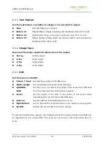
Страница 29: ...e LPMVC CL025M is possible by multiples of 128 and horizontal width is possible by multiples of 64 The starting position of the Y axis and Vertical width is possible by multiples of 2 5 2 Test Pattern...

Страница 30: ...the exposure time beyond the scope of the set frame rate it is automatically changed to the maximum frame rate to satisfy the exposure time entered by the user so user should be careful Model LPMVC CL...

Страница 31: ...nce of the illuminance in the sensor manufacturing process 5 8 Black Level Compensation If the temperature of the sensor rises the sharpness of the image quality will fall because of the Blurred Image...

Страница 32: ...amera Output Timing Chart Figure 17 and 18 show the Horizontal Timing Chart of LPMVC CL025M Figure 19 and 20 show the Vertical Timing Chart of LPMVC CL025M 5 9 1 Horizontal Timing Chart Figure 18 Hori...

Страница 33: ...LPMVC CL025M Manual More than Imaging Laon People 33 2016 03 04 Figure 20 Horizontal Timing Chart of 8Tap...

Страница 34: ...LPMVC CL025M Manual More than Imaging Laon People 34 2016 03 04 Figure 21 Horizontal Timing Chart of 10Tap...

Страница 35: ...LPMVC CL025M Manual More than Imaging Laon People 35 2016 03 04 5 9 2 Vertical Timing Chart Figure 22 Vertical Timing Chart of 2Tap Figure 23 Vertical Timing Chart of 4Tap...

Страница 36: ...LPMVC CL025M Manual More than Imaging Laon People 36 2016 03 04 Figure 24 Vertical Timing Chart of 8Tap Figure 25 Vertical Timing Chart of 10Tap...

Страница 37: ...from the External Trigger port or CC1 port of the camera Trigger Polarity This item decides to operate the camera in the Active High or in the Active Low when the trigger signal is input Pulse Width T...

Страница 38: ...image data transmission time 5 10 2 External Sync Mode Pulse Width Trigger In the External Sync Mode the Camera maintains the standby status until the external trigger signal is input and then exposes...

Страница 39: ...reset Trigger Mode User should select the Trigger Source by the External Trigger port or the CC1 port and should set the Sensor Exposure Time to the Edge Preset Trigger In Edge Preset Trigger Mode it...

Страница 40: ...osure progress simultaneously In this mode the maximum frame rate of the camera can be used because it can be used effectively when the frame rate is very fast or the exposure time of the sensor is no...

Страница 41: ...exposure Strobe Bypass Sync This item passes the CC3 external light signal as it is passed Strobe Polarity This item decides to operate the strobe signal as Active High or in the Active Low Strobe Del...

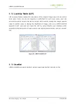
Страница 42: ...ect the ad hoc input to the ad hoc output LUT is used to change the image s specific value to another value or change the brightness of image and so on LPMVC CL025M supports 8 LUT and user can make th...

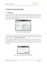
Страница 43: ...ure 27 Figure 32 CULaTor UART Select Dialog In this dialog box the physical COM Port which is searched in the user s computer and the List of the virtual COM Ports these are used in the CameraLink sta...

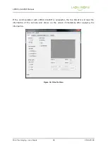
Страница 44: ...maging Laon People 44 2016 03 04 If the communication with LPMVC CL025M is successful the the CULaTor will read the information of the camera and shows on the screen immediately after applying the inf...

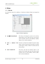
Страница 45: ...ll set values that user did not save will be canceled and the saved StartUp UserSet PRNU LUT are will be maintained Load UserSet from file This menu will load the UserSet file saved in shape of the in...

Страница 46: ...the ini file This menu will be useful in the work environment in which a number of cameras use the same settings Save UserSet x This menu will saved in the UserSet All set values that user did not sa...

Страница 47: ...mediately after the camera power is applied User can set the StartUp movement of the camera by selecting the item from Factory Default and 8 UserSet When the save is completed the StartUp save complet...

Страница 48: ...LPMVC CL025M Manual More than Imaging Laon People 48 2016 03 04 6 2 3 About Figure 39 CULaTor About Menu Figure 40 CULaTor About Dialog Copyright Camera Image Tap CULaTor Version Camera Version...

Страница 49: ...e output to 10 bit 6 3 2 View Mode Set the Playback Mode Normal Set the Normal Playback Mode rather than ROI Binning ROI Playback Mode that can increase the Frame Rate by setting the image output area...

Страница 50: ...output 2 Tap 2 Tap output 6 3 5 ROI Set the region on the ROI X Start Y Start Set starting position of the ROI area Width Height Set horizontal vertical size of the ROI area QUARTER HALF Set the 1 4 o...

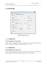
Страница 51: ...mera If user raises the Analog Gain value of the camera the screen will be brighter than before The range of the Gain value that can be set are 0 1 2 3 6 4 2 Digital Gain Set the Digital Gain of the c...

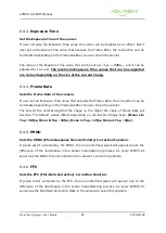
Страница 52: ...depending on the Frame Grabber So user should be careful The shorter the vertical length of the image is the higher the value of Frame Rate will become The default values differs depending on current...

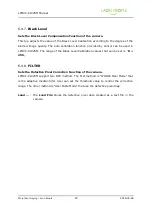
Страница 53: ...n be used in LPMVC CL025M The range of the Black Level Calibration values that can be set is 0 255 6 4 8 FILTER Sets the Defective Pixel Correction Function of the camera LPMVC CL025M support two DPC...

Страница 54: ...ger Off Terminates the Trigger Mode External Trigger Use the Trigger Mode and the Input pin of I O port Board Control Trigger Use the Trigger Mode and the frame grabber s CC1 port 6 5 2 Trigger Polari...

Страница 55: ...ter the set time has passed 6 5 5 Strobe Strobe On Use the external light source Sensor Exposure Sync Activates the external light source at the same time with the beginning of the sensor exposure Str...

Страница 56: ...drive the Strobe before starting the exposure of the sensor this tab sets the interval time between the Strobe and the beginning of the sensor exposure time 6 5 8 Strobe Duration Set the duration tim...

Страница 57: ...e user can change the output data from the particular area or all the brightness values of the output to the value of a user specified arbitrary image data Figure 46 CULaTor LUT Tab 6 6 1 LUT On Decid...

Страница 58: ...ice is clicked on the CULaTor s LUT Tab the CULaTor opens save device dialog box User can select the LUT data and adjust the LUT sequence User can write the select LUT value to EEPROM Figure 47 CULaTo...

Страница 59: ...LPMVC CL025M Manual More than Imaging Laon People 59 2016 03 04 6 6 7 Set to Linear Set the Knee Points as the default value The LUT formula that corresponds to the default value is y x...

Отзывы: