background image

C: Connections and Pinouts 


 XPress™ DR Industrial Device Server User Guide 

86 

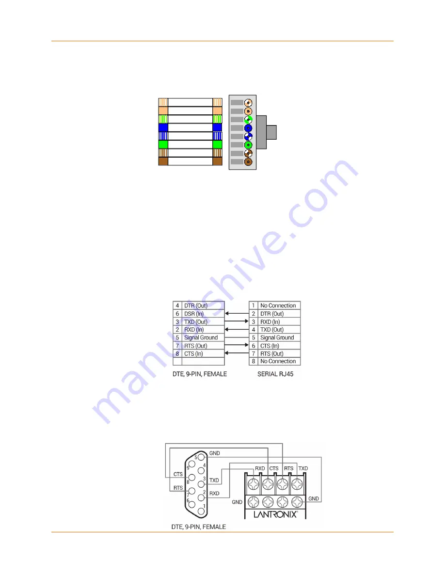
The next drawing shows a typical RJ-45 connector. The color is not standard but very typical of 

an Ethernet Patch cable. Pin 1 is located at the top of the connector ( White). The view 

is from the end of the connector.  

Figure C-2 RJ-45 Connector 


Serial Interface Connections 

The serial device can be RS-232 or RS-485/422 and the connections can be screw terminals or 

RJ-45 connector. This section shows several practical methods for making the hardware 

connections. The following diagrams show typical interface cables for the RS-232 Serial interface 

and the Ethernet interface.  

9-Pin RS-232 to Serial RJ-45 

The cable diagram below is for connecting a PC (com port) to the XPress DR serial RJ45 port.  

You can use the serial RJ45 port to configure and test port settings prior to connection to your 

automation device. 

Figure C-3 RS-232 to Serial RJ-45 Connection 


9-Pin RS-232 to Serial Screw Terminals 

This connection assumes you are connecting a typical PC (COM1) to the XPress DR through the 

serial screw terminals.    

Figure C-4 RS-232 Configuration 


 White
Orange
Green + White
Blue
Blue + White
Green
Brown + White
Brown

View from

Connector End

Содержание XPress DR

Страница 1: ...Part Number 900 772 R Revision C December 2017 XPress DR Industrial Device Server User Guide ...

Страница 2: ...Lantronix undertakes no obligation to update the information in this publication Lantronix does not make and specifically disclaims all warranties of any kind expressed implied or otherwise regarding title non infringement fitness quality accuracy completeness usefulness suitability or performance of the information provided herein Lantronix shall have no liability whatsoever to any user for any d...

Страница 3: ...ority to operate the device The information in this guide may change without notice The manufacturer assumes no responsibility for any errors which may appear in this guide Revision History Date Rev Comments February 2016 A Initial release May 2016 B Included Limited Power Source LPS information December 2017 C Updated enhanced password information ...

Страница 4: ...________ 15 Network Protocols Standard Tunneling ______________________________ 15 Additional Features _____________________________________________________ 15 Packing Algorithm________________________________________________ 15 IP Address _____________________________________________________ 15 Port Number ____________________________________________________ 16 Configuration Methods _____________...

Страница 5: ...___________ 35 Channel 1 Connection Configuration ______________________________________ 37 Connection Settings TCP_________________________________________ 37 Connection Settings UDP_________________________________________ 40 6 Configuration via Telnet or Serial Port Setup Mode 42 Accessing the Setup Mode Window ________________________________________ 42 Telnet Connection ______________________...

Страница 6: ...____________ 57 TCP Re Transmission Timeout _____________________________________ 58 Enable alternate MAC ____________________________________________ 58 Ethernet Connection Type _________________________________________ 58 Security Settings Option 6 _______________________________________________ 58 Disable SNMP __________________________________________________ 58 SNMP Community Name ___________...

Страница 7: ...___________ 77 Interface Mode __________________________________________________ 77 Baud Rate______________________________________________________ 78 Flow Control ____________________________________________________ 78 Connect Mode __________________________________________________ 79 Disconnect Mode ________________________________________________ 79 Flush Mode Buffer Flushing __________________...

Страница 8: ...____________________________ 92 Broadcast Address _______________________________________________ 92 IP Netmask _____________________________________________________ 92 Private IP Networks and the Internet _________________________________ 93 Network RFCs __________________________________________________ 93 BOOTP ______________________________________________________________ 94 ARP and Telnet ___...

Страница 9: ...rial Screw Terminal Pinouts ___________________________________ 85 Figure C 2 RJ 45 Connector ______________________________________________ 86 Figure C 3 RS 232 to Serial RJ 45 Connection _______________________________ 86 Figure C 4 RS 232 Configuration __________________________________________ 86 Figure C 5 Front Panel Layout ____________________________________________ 87 Figure C 6 Power Req...

Страница 10: ..._______ 78 Table B 9 Connect Mode Options __________________________________________ 79 Table B 10 Disconnect Mode Options_______________________________________ 79 Table B 11 Flush Mode Options ___________________________________________ 80 Table B 12 Pack Control Options __________________________________________ 81 Table B 13 Network Portion of IP Address ___________________________________ 81 ...

Страница 11: ...the current configuration using DeviceInstaller application 5 Configuration Using Web Manager Details using the Web Manager to set parameters such as port and server properties 6 Configuration via Telnet or Serial Port Setup Mode Provides instructions for accessing Setup Mode command line interface using a Telnet connection through the network or a terminal or terminal emulation program through th...

Страница 12: ...he XPress DR device server and setting it up with the Com Port Redirector See http ltxfaq custhelp com app answers detail a_id 1119 Com Port Redirector Quick Start Guide Provides information on using the Windows operating system based utility to create a virtual com port B Network Configuration Using UDP Describes how to configure and query the device server over the network using UDP datagrams C ...

Страница 13: ...llers Data Collection Devices Universal Power Supply UPS Management Units Telecommunications Equipment Data Display Devices Security Alarms and Access Control Devices Handheld Instruments Modems The XPress DR connects these devices through a TCP data channel or through a Telnet connection to computers or another device server Datagrams can be sent by UDP Figure 2 1 XPress DR The XPress DR supports...

Страница 14: ...the plant throughout the facility or across the global enterprise The following picture is one of the device servers in the IAP family Figure 2 1 RS 485 Multidrop with XPress DR IAP Lantronix provides IAP device servers are specifically designed for different industrial environments XPress DR IAP with DIN rail interface for harsh environments or alongside control instruments in electrical panels U...

Страница 15: ...pgrades Network Protocols Standard Tunneling The XPress DR uses TCP IP protocols for network communication The supported standards are ARP UDP TCP ICMP Telnet TFTP DHCP AutoIP and SNMP For transparent connections TCP IP binary stream or Telnet protocols are used Firmware upgrades can be made with the TFTP protocol The IP Internet Protocol protocol defines addressing routing and data block handling...

Страница 16: ...ation the XPress DR requires configuration For the unit to operate correctly on a network it must have a unique IP address on the network There are three basic methods for logging into the XPress DR and assigning IP addresses and other configurable settings DeviceInstaller Configure the IP address and other network settings on the XPress DR using a Graphical User Interface GUI on a PC attached to ...

Страница 17: ...Information Label The product information label on your XPress DR or XPress DR IAP industrial device server contains important information about your unit Figure 2 4 Product Information Label Notes Before mounting the device on a DIN rail copy the information from the label ...

Страница 18: ... remove the web pages and change the configure dialogs See the user manuals on individual protocols for protocol specific settings and configuration dialogs Protocol manuals are found at www lantronix com downloads This section describes the setup and configuration dialogs for the Standard Tunnel Protocol Note The following information is based on the condition that a XPress DR is loaded with Stan...

Страница 19: ...s DR device server must have a unique IP address on your network This address references the specific unit By default the unit is DHCP enabled and automatically assigned an IP address on DHCP enabled networks If you are assigning a static IP address the systems administrator generally provides the IP address subnet mask and gateway Note The factory default IP address is 0 0 0 0 to enable DHCP BOOT...

Страница 20: ...ork settings at a command prompt using a UNIX or Windows based system Only one person at a time can be logged into the configuration port port 9999 This eliminates the possibility of several people simultaneously attempting to configure the unit See ARP and Telnet AutoIP This automatic method is appropriate when you have a small group of hosts rather than a large network This method allows the hos...

Страница 21: ...lick Start All Programs Lantronix DeviceInstaller 4 4 DeviceInstaller If your PC has more than one network adapter a message displays Select an adapter and click OK Note If the unit already has an IP address e g DHCP has assigned an IP address click the Search icon and select the unit from the list of Lantronix device servers on the local network 2 Click the Assign IP icon 3 If prompted enter the ...

Страница 22: ...iguration DeviceInstaller provides a view of the unit s configuration 1 Follow the instructions above to locate the XPress device server 2 In the right pane click the Device Info tab The current XPress device server configuration displays Table 4 1 XPress DR Configuration in DeviceInstaller Current Settings Description Name Configurable field A name that identifies the XPress The name field is bla...

Страница 23: ...ssigning an IP Address Gateway Non configurable field Displays the XPress device server s current gateway To change the gateway see Assigning an IP Address Number of COB partitions supported Non configurable field Displays the number of COB partitions supported Number of Serial Ports Non configurable field Displays the number of serial ports on the XPress unit TCP Keepalive Non configurable field ...

Страница 24: ...plays Continue with Chapter 6 Configuration via Telnet or Serial Port Setup Mode Assigning the IP Address Serial Port Login To assign the IP address and other network settings using a serial connection 1 Connect a console terminal or a PC running a terminal emulation program to the unit s serial port The default serial port settings are 9600 baud 8 bits no parity 1 stop bit no flow control 2 To en...

Страница 25: ... Accessing the XPress Device Server Using DeviceInstaller 2 Click View Setup Record File in the DeviceInstaller menu bar 3 Double click to select the desired setup record file 4 A View Setup Records window opens showing contents of the configuration file Updating Configuration Device configuration information can be saved in a file and later used to update the configuration of other devices To upd...

Страница 26: ...ew firmware click Browse to browse to the firmware file and click Next to advance to Step 3 of 5 5 Check Install setup records from a file click Browse to browse to and select desired setup record file and click Next to advance to Step 4 of 5 6 Click Save Installation browse to and save to a desired save location and click Next to advance to Step 5 of 5 ...

Страница 27: ...e Server User Guide 27 7 Click Next to upgrade your device or Cancel to cancel Status of your device update will appear in the Device Upgrade Wizard with a confirmation appearing once the unit is updated 8 Click Close to exit the Device Upgrade Wizard ...

Страница 28: ...ice Your device may have different configuration options Web Manager Page Note The XPress DR IAP may not have a web page or may use a different format web page You can start a web browser for configuration by opening your JAVA enabled web browser and entering the IP address or by clicking the Web Configuration button on the Device Management window There is initially no Web Manager password for yo...

Страница 29: ...h page does not change the configuration on the device Clicking the OK button tells the XPress DR device server what changes to use the Apply Settings button makes the changes permanent and reboots the XPress DR unit Apply Defaults 1 Click Apply Defaults to set the device server back to the default settings 2 Click Yes to set factory settings or click No to cancel Figure 5 2 Apply Settings and App...

Страница 30: ...network connectivity BOOTP Select Enable to permit the Bootstrap Protocol BOOTP server to assign the IP address from a pool of addresses automatically Enable is the default DHCP Select Enable to permit the Dynamic Host Configuration Protocol DHCP to assign a leased IP address to the XPress unit automatically Enable is the default AutoIP Select Enable to permit the Automatic Private IP Addressing A...

Страница 31: ...ork DNS Server The DNS server allows the name of a remote machine to be resolved automatically Enter the IP address of the DNS server If the device is DHCP enabled the DHCP server provides the DNS server IP address which will override this configured value Note This setting is applicable only in Manual Connection mode 4 When you are finished click the OK button 5 Click Apply Settings in the Naviga...

Страница 32: ...nable advanced password Enable selecting this option enables advanced password creation allowing you to create passwords up to 16 bytes in length Disable selecting this option disables advanced password creation allowing you to create basic passwords up to 4 bytes in length Telnet Web Manager Password Enter the password required for Telnet configuration and Web Manager access No password or enteri...

Страница 33: ...received during the device server s initialization at startup The default setting is Enable HTTP Server Port This option allows the configuration of the web server port number The valid range is 1 65535 The default setting is 80 Config Server Port Not applicable for this product MTU Size The Maximum Transmission Unit MTU is the largest physical packet size a network can transmit for TCP and UDP En...

Страница 34: ...bled for Manual and Modem Mode The unit does not accept a data connection from a remote device when the hostlist option is enabled To configure the host list 1 In the Navigation bar click Hostlist Figure 5 5 Hostlist Settings 2 Update the following Retry Settings Retry Counter Enter the value for the number of times the XPress device server should attempt to retry connecting to the host list The d...

Страница 35: ...ettings 5 Update the following Channel 1 Disable Serial Port When selected disables communication through the serial port The serial port is enabled by default Note This feature is not available on single port device servers since it can only be applied to channel 1 Port Settings Protocol From the drop down menu select the protocol type for the selected channel The default setting is RS232 Flow Co...

Страница 36: ...work and is especially useful in applications in a routed Wide Area Network WAN Adjusting parameters in this mode can economize the network data stream Disabled by default Idle Gap Time Select the maximum time for inactivity The default time is 12 milliseconds Match 2 Byte Sequence Use to indicate the end of a series of data to be sent as one group The sequence must occur sequentially to indicate ...

Страница 37: ...sive Connect Select Yes to clear the output buffer with a connection initiated from the network to the device The default setting is No At Time of Disconnect Select Yes to clear the output buffer when the network connection to or from the device is disconnected The default setting is No 6 When you are finished click the OK button 7 Click Apply Settings in the Navigation bar Channel 1 Connection Co...

Страница 38: ...port With Active Mdm Ctrl In Accepts external connection requests only when the Modem Control In input is asserted With Start Character Attempts to connect when it receives a specific start character from the serial port The default start character is carriage return Manual Connection Attempts to connect when directed by a command string received from the serial port Auto Start Automatically conne...

Страница 39: ...to connect to any others If this connection fails the unit continues to scroll through the table until it connects to another IP in the host list The host list is disabled for Manual Mode and for Modem Mode The unit will not accept a data connection from a remote device when the host list option is enabled LED Select Blink for the status LEDs to blink upon connection or None for no LED output The ...

Страница 40: ...available fields enter or modify the following information Figure 5 8 UDP Connection Settings Connect Protocol Protocol Select UDP from the drop down menu Datagram Mode Datagram Type Configures the remote IP or network broadcast address and the remote port Enter 01 for directed or broadcast UDP The default setting is 00 Accept Incoming Select Yes to accept incoming UDP datagrams The default settin...

Страница 41: ...is not to broadcast Note Datagrams are sent as subnet directed broadcasts Device Address Table The table is enabled when Datagram Type is set to FD Enter Dev Addr values between 1 and 255 to identify units on the local network of device servers Note Lantronix Tech Support supports Datagram type 01 Datagram Type FD is for OEM use 3 When you are finished click the OK button 4 Click Apply Settings in...

Страница 42: ... complete the configuration continue with chapters 7 Setup Mode Server Configuration 8 Channel Mode Channel Configuration and 9 Setup Mode Advanced Settings Note The menus in the configuration chapters show a typical device Your device may have different configuration options Accessing the Setup Mode Window Telnet Connection To configure the unit over the network establish a Telnet connection to p...

Страница 43: ... 172 19 0 1 DNS Server not set DHCP FQDN option Disabled Security SNMP is enabled SNMP Community Name public Telnet Setup is enabled TFTP Download is enabled Port 77FEh is enabled 77FEh Access Mode is Read Write Web Server is enabled Web Setup is enabled ECHO is disabled Enhanced Password is disabled Channel 1 Baudrate 9600 I F Mode 4C Flow 00 Port 10001 Connect Mode C0 Send in Modem Mode enabled ...

Страница 44: ... up the self test begins and the red Diagnostic LED starts blinking You have one second to enter three lowercase x characters xxx Note The easiest way to enter Setup Mode is to hold down the x key at the terminal or emulation while powering up the unit 3 At this point the screen display is the same as when you use a Telnet connection To continue with a serial port login go to Telnet Connection Exi...

Страница 45: ...ess 000 000 000 000 _ If DHCP is used the third octet of the IP address sets the BootP DHCP AutoIP options The following table shows the bits you can manually configure to force the XPress DR device server to disable AutoIP DHCP or BootP To disable an option set the appropriate bit Table 7 1 BootP DHCP AutoIP Options Options Bit Value AutoIP 0 1 DHCP 1 2 BootP 2 4 For example if the third octet is...

Страница 46: ...Network Class Host Bits Netmask A 24 255 0 0 0 B 16 255 255 0 0 C 8 255 255 255 0 Table 7 3 Netmask Examples Netmask Host Bits 255 255 255 252 2 255 255 255 248 3 255 255 255 240 4 255 255 255 224 5 255 255 255 192 6 255 255 255 128 7 255 255 255 0 8 255 255 254 0 9 255 255 252 0 10 255 255 248 0 11 255 128 0 0 23 255 0 0 0 24 Set DNS Server IP Address The DNS server allows the name of a remote ma...

Страница 47: ...de from the serial port with network connection enabled and issue the NC Network Communication command you see the unit s IP configuration There are three methods for assigning DHCP names to the unit Default DHCP Name If you do not change the DHCP name and you are using an IP of 0 0 0 0 then the DHCP name defaults to XX XX XX XX XXXXXX is the last 6 digits of the MAC address shown on the label on ...

Страница 48: ... RING Y Auto increment source port N Remote IP Address 000 000 000 000 Remote Port 0 DisConnMode 40 Telnet Com Port Cntrl Enabled FlushMode 00 DisConnTime 00 00 SendChar 1 00 SendChar 2 00 Terminal name Using this option define how the serial port will respond to network and serial communications Baudrate The unit and attached serial device such as a modem must agree on a speed or baud rate to use...

Страница 49: ...Mode settings Table 8 2 Common Interface Mode Settings Common I F Mode Setting Binary Hex RS 232C 8 bit No Parity 1 stop bit 1 0100 1100 4C RS 232C 7 bit Even Parity 1 stop bit 1 0111 1000 78 RS 485 2 Wire 8 bit No Parity 1 stop bit 1 0100 1111 4F RS 422 8 bit Odd Parity 1 stop bit 1 0101 1101 5D 1 The XPress DR requires you to choose the correct setting in the IF mode and to also set the front pa...

Страница 50: ... numbers for this setting as incorrect operation may result Use Port 0 for the outgoing local port to change with each connection The port range is 50 000 59 999 Each subsequent connection increments the number by 1 it wraps back around to 50 000 Only use this automatic port increment feature to initiate a connection using TCP Set the port to a non zero value when the unit is in a passive mode or ...

Страница 51: ...is 1234 C121 2 4 5 1 Complete override connection is started with host 121 2 4 5 port 1 C5 Connect to 129 1 2 5 port 1234 C28 10 12 Connect to 129 1 28 10 port 12 C0 0 0 0 0 Enters Monitor Mode Cwww lantronix com 80 Tries to connect to the Lantronix web server if the hostname domain www lantronix com is configured in the DNS server database Autostart Automatic Connection If you enable Autostart th...

Страница 52: ...hat was typed To disconnect a connection using Modem Mode commands There must be 1 second guardtime no data traffic before sending There must not be a break longer that 1 second between s There must be another 1 second guardtime after the last is sent The unit acknowledges with an OK to indicate that it is in command mode Enter ATH and press Enter It is echoed if echo is enabled ATH is acknowledge...

Страница 53: ...w the IP address Auto Increment Source Port Auto increment source port N _ Y Yes auto increment the source port The XPress DR increments the port number used with each new connection Remote IP Address This is the destination IP address used with an outgoing connection Remote IP Address 000 000 000 000 Remote Port The remote TCP port number must be set for the unit to make outgoing connections This...

Страница 54: ... two different packing algorithms FlushMode 00 Note See Table F 1 Binary to Hexadecimal Conversion Table Table 8 9 Flush Mode Options Function 7 6 5 4 3 2 1 0 Input Buffer Serial to Network Clear with a connection that is initiated from the XPress DR to the network 1 Clear with a connection initiated from the network to the XPress DR 1 Clear when the network connection to or from the XPress DR is ...

Страница 55: ...her trailing characters follow the end of sequence character this option helps to adapt frame transmission to the frame boundary Send Characters If 2 Byte Send Character Sequence is enabled the unit interprets the sendchars as a 2 byte sequence if not set they are interpreted independently If Send Immediately After Characters is not set any characters already in the serial buffer are included in t...

Страница 56: ...f the characters Alternatively the two characters can be interpreted as a sequence SendChar 1 00 _ SendChar 2 00 _ Telnet Terminal Type This parameter appears only if the terminal type option is enabled in Disconnect Mode see DisConnMode above If this option is enabled you can use the terminal name for the Telnet terminal type Enter only one name Terminal name If the terminal type option is enable...

Страница 57: ...5s 0s disable 45 ARP Cache timeout in s Whenever the unit communicates with another device on the network it will add an entry into its ARP table The ARP Cache timeout option allows you to define how many seconds 1 600 the unit will wait before timing out this table ARP Cache timeout in s 0s 600s 600 Disable Monitor Mode at Bootup This option allows you to disable all entries into Monitor Mode dur...

Страница 58: ...or auto negotiation default To select the speed and duplex enter one of the following 2 10Mbit half duplex 3 10Mbit full duplex 4 100Mbit half duplex or 5 100Mbit full duplex Ethernet connection type 0 _ Security Settings Option 6 Note You can change these settings via Telnet or serial connections only not on the Web Manager We recommend that you set security over the dedicated network or over the...

Страница 59: ...etting that allows DeviceInstaller Web Pages and custom programs to configure the unit remotely You may wish to disable this capability for security purposes For more information about remote configuration see the Lantronix Embedded Integration Kit User Guide at the Lantronix Web site www lantronix com downloads Disable Port 77FEh N The default setting is the N No option which enables remote confi...

Страница 60: ...lnet and Web Page access We recommend that you select the Y Yes option and enable the enhanced password setting Avoid using either the 4 character basic password setting or no password at all as they are not secure options Enable Enhanced Password N Default Settings Option 7 Select 7 to reset the unit s Channel 1 and Enhanced Security to the factory default settings The server configurations IP ad...

Страница 61: ...r unit or via the serial port You can also update the unit s internal web interface cob via tftp or deviceinstaller The firmware files can be found at www lantronix com downloads and are installed in the Program Files DeviceInstaller Firmware folder Here is a list of typical names for those files Check the Lantronix web site for the latest versions and release notes Table 10 1 Protocol Firmware Fo...

Страница 62: ...vailable for download at www lantronix com downloads Before you can load firmware through the serial port you need to convert the ROM code to HEX format There is a DOS application R2H EXE that can be used to convert the ROM file to HEX format The R2H EXE application is available at ftp ftp lantronix com pub Put R2H EXE and the ROM file into the same directory on a PC then open a DOS Window to that...

Страница 63: ...ived the unit checks the integrity of the firmware image before programming the new firmware in the flash ROM The following message displays when the firmware upgrade is complete NodeSet 2 0 0 DL 02049 lines loaded Note You can only update your unit s internal Web interface using TFTP or DeviceInstaller ...

Страница 64: ...stablish a Telnet session to the configuration port 9999 The following message appears MAC address 0080A38BFC08 Software version V6 11 0 1 160127 XPressDR Press Enter for Setup Mode An 0 prompt indicates that you have successfully entered Monitor Mode Monitor Mode Commands The following commands are available in Monitor Mode Many commands have an IP address as an optional parameter xxx xxx xxx xxx...

Страница 65: ...record must still be written but the encryption specific bytes do not need to be provided they can be null since they are not overwritten SA Scan Initiates a wireless scan if the wireless interface is enabled Reports any stations found including BSSID SSID and RSSI If SA is followed by a string the string is used to filter SSIDs before reporting If the BSS does not broadcast its SSID only the BSSI...

Страница 66: ...ring any of the commands listed above will generate one of the following command response codes Table 11 2 Command Response Codes Response Meaning 0 OK no error 1 No answer from remote device 2 Cannot reach remote device or no answer 8 Wrong parameter s 9 Invalid command ...

Страница 67: ...s allows a modem on a server to be shared by many PC users thus the name of modem sharing which is commonly used to describe this The Redirector support both IP and IPX For IP you must have IP installed and bound to your network card and a server which supports TCP socket connections to its serial ports For IPX you must have IPX SPX installed and bound to your network card and the server must supp...

Страница 68: ...ivity network Random Flashing TXD Yellow Transmitting serially Flashes during transmit RXD Yellow Receiving serially Flashes during receive F Red Fault in XPress DR communication read error or XPress DR is in Configuration Mode Simultaneously lit F Red and R Green LEDs mean something is wrong If the F Red LED is lit or blinking count the number of times the R Green LED blinks between its pauses Si...

Страница 69: ...it to lose the IP address Telnet back into Port 1 Wait for it to fail then Telnet to port 9999 again Make sure you press Enter quickly When you Telnet to port 9999 the message Press Enter to go into Setup Mode displays However nothing happens when you press Enter or your connection is closed You did not press Enter quickly enough You only have 5 seconds to press Enter before the connection is clos...

Страница 70: ... settings for the device server are RS232 9600 Baud 8 Character Bits No Parity 1 Stop Bit No Flow Control When you try to enter the setup mode on the device server via the serial port you get no response The issue will most likely be something covered in the previous problem or possibly you have Caps Lock on Double check everything in the problem above Confirm that Caps Lock is not on You can ping...

Страница 71: ...8 77FEh on the device server Make sure that port 30718 77FEh is not blocked with any router that you are using on the network Also make sure that port 77FEh is not disabled within the Security settings of the device server Lantronix Technical Support Lantronix offers many resources to support our customers and products at www lantronix com support For instance you can ask a question find firmware ...

Страница 72: ... 3Q F6 Query for Firmware Version None The device server responds with the F7 block below F7 Firmware Information First 16 bytes of the firmware image and 4 bytes device information and mac address The first 16 bytes of the firmware image contain the software type offset 4 5 and checksum offset 14 15 The last two bytes of the device information contain the mac address F8 Query for Setup Record Non...

Страница 73: ...vice servers from a master device server via cut and paste or UDP see Network Configuration Using UDP Device servers use a 120 byte setup record in Intel Hex format This format facilitates the transfer of binary data using ASCII characters See Setup Records and The Intel Hex Format for information about setup records and converting them to Intel Hex format Figure B 1 Sample Setup Record in Intel H...

Страница 74: ...x record see The Intel Hex Format 3 Copy the setup record into a text file and save it for future use To request the setup record of a properly configured device server via UDP 1 Configure a device server with the desired parameters and place it on the network 2 From a host PC send the F8 datagram to the device server see Network Configuration Using UDP The device server responds with the F9 datag...

Страница 75: ...000001FF End record type 01 length 00 address 00 00 checksum FF 01002000805F Data record consisting of one byte value 80 Hex for address 0020 32 decimal For communication with the node the following block types are defined Table B 2 Block Types Option Hex Data block program memory firmware 00 End record 01 Data block configuration memory 10 To get and set the node configuration 120 bytes should be...

Страница 76: ... transmitted at once from and to the node Unused bytes should be initialized as 00 Table B 3 Setup Record Construction defines the structure of a setup record Table B 3 Setup Record Construction Byte s Function 00 03 IP address of the unit x x x x 04 Reserved 0 05 Flag BYTE Bit 7 Reserved 0 Bit 6 Set 1 for AUI 0 for 10BASE T CoBox Micro only Bits 5 0 Reserved 0 06 Number of host bits for subnettin...

Страница 77: ...2 33 Characters to trigger send immediately sendchar 34 Flush mode see Table B 11 Flush Mode Options 35 Pack Control see Table B 12 Pack Control Options 36 47 Reserved 0 48 63 a Terminal name for Telnet terminal type option 15 characters max 0 terminated If set and Bit 6 in Disconnect Mode is set Telnet connection will be assumed b Password for Passworded Socket Connection Bit 4 in Disconnect Mode...

Страница 78: ... The device server and attached serial device must agree on a speed or baud rate to use for the serial connection Use the following table to select Baud Rate settings Table B 7 Baud Rate Settings Speed bps Hex 38400 00 19200 01 9600 02 4800 03 2400 04 1200 05 600 06 300 07 115200 08 57600 09 Flow Control Flow control sets the local handshaking method for stopping serial input output Generally flow...

Страница 79: ...reachable 1 Startup No active startup 0 0 0 0 With any character 0 0 0 1 With active DTR 1 0 0 1 0 With CR 0x0D only 0 0 1 1 Manual connection 0 1 0 0 Autostart 0 1 0 1 Datagram Type Directed UDP 1 1 0 0 Modem Mode Full Verbose 1 0 1 1 0 Without Echo 0 0 1 1 0 1 character Response 1 0 1 1 1 1 Inactive DTR is hardwired to 12VDC Note See Table 11 1 Binary to Hexadecimal Conversion Table Disconnect M...

Страница 80: ...to 12VDC This option is disabled in the XPress DR Note See Table 11 1 Binary to Hexadecimal Conversion Table Flush Mode Buffer Flushing Using this parameter you can control line handling and network buffers with connection startup and disconnect You can also select between two different packing algorithms Use the following table to select Flush Mode options Table B 11 Flush Mode Options Function 7...

Страница 81: ...s a unique IP address This address provides the information needed to forward packets on the local network and across multiple networks if necessary IP addresses are specified as x x x x where each x is a number from 1 to 254 for example 192 0 1 99 The device server must be assigned a unique IP address to use TCP IP network functionality IP addresses contain three pieces of information the network...

Страница 82: ...sts on their own sub network All packets destined for other subnets are sent to a router on the local network Host Portion The host portion of the IP address is a unique number assigned to identify the host Network Address A host address with all host bits set to 0 addresses the network as a whole for example in routing entries 192 168 0 0 Broadcast Address A host address with all host bits set to...

Страница 83: ...orks and the Internet If your network is not and will not be connected to the Internet you may use any IP address If your network is connected or will be connected to the Internet or if you intend to operate the device server on an intranet you should use one of the reserved sub networks Consult your network administrator with questions about IP address assignment Network RFCs For more information...

Страница 84: ...J 45 Serial Connector The serial RJ 45 serial connector supports up to 115200 bits per second and has the following signals Table C 1 Serial RJ45 Pinouts Pin Direction Name Function 1 Not Connected None 2 Hard wired output DTR DTR Data Terminal Ready 3 To XPress DR RXD or RX RS 232 RXD Received Data RS 422 485 RX Received Data 4 From XPress DR TXD or TX RS 232 TXD Transmit Data RS 422 485 TX Trans...

Страница 85: ...ust be connected together Note Termination resistors R 120 Ohm are used to match impedance of a node to the impedance of the transmission TX line Termination resistors should be placed only at the extreme ends of the data line and no more than two terminations should be placed in any single segment of a RS 485 network The terminator resistors may not be needed for your application RJ 45 Ethernet I...

Страница 86: ...or making the hardware connections The following diagrams show typical interface cables for the RS 232 Serial interface and the Ethernet interface 9 Pin RS 232 to Serial RJ 45 The cable diagram below is for connecting a PC com port to the XPress DR serial RJ45 port You can use the serial RJ45 port to configure and test port settings prior to connection to your automation device Figure C 3 RS 232 t...

Страница 87: ...User Guide 87 Front Panel Description The following figure illustrates the screw block connector pinouts and other components of the XPress DR See Table C 4 Front Panel Components for explanations corresponding to the circled numbers Figure C 5 Front Panel Layout ...

Страница 88: ...d error or XPress DR is in Configuration Mode 11 LED Green Ready SOLID Ready Flashing Error Message 12 LED Yellow Activity FLASHING Network traffic 13 LED Green Link SOLID XPress DR has good Ethernet link 14 Connector RJ45 Ethernet port RJ45 connector for Ethernet 10BaseT 15 Connector RJ45 Serial port RJ45 connector for RS 232 RS 422 485 16 LED Yellow Serial TXD FLASHING Indicates transmission fro...

Страница 89: ... Limited Power Source LPS between 9 30 VDC or 9 24 VAC can be used The unit requires a maximum of 3 Watts Figure C 6 Power Requirements Reset Switch The unit has a reset switch located on the front panel above the red LED Figure C 7 Reset Switch RS 232 RS 485 Switch This switch controls the type of serial interface used by the serial RJ45 connector Set this switch for RS 232 Up or RS 485 Down Figu...

Страница 90: ...perating range 0 to 60 C 32 to 140 F Humidity 20 to 90 RH non condensing Case High Impact Plastic case designed for DIN Rail 35mm Protocols Supported ARP UDP IP TCP IP Telnet ICMP SNMP DHCP BOOTP TFTP and HTTP Network Interface 10Base T 100Base TX Ethernet RJ45 connector Serial Line Formats Characters 7 or 8 data bits Stop bits 1 or 2 Parity odd even none Modem Control DTR DCD CTS RTS Flow Control...

Страница 91: ...iguration AutoIP The unit ships with a default IP address of 0 0 0 0 which automatically enables Auto IP within the unit AutoIP is an alternative to DHCP that allows hosts to automatically obtain an IP address in smaller networks that may not have a DHCP server A range of IP addresses from 169 254 0 1 to 169 254 255 254 has been explicitly reserved for AutoIP enabled devices The range of Auto IP a...

Страница 92: ...es are most common and are often used in small companies These networks can consist of a maximum number of 254 hosts Example 192 7 1 9 network 192 7 1 host 9 The remaining addresses 224 x x x 239 x x x are defined as class D and are used as multicast addresses The addresses 240 x x x 254 x x x are defined as class E and are reserved addresses Network Address The host address with all host bits set...

Страница 93: ...tion you may use any IP address you wish If your network is not connected to the Internet and you have plans to connect or you are connected to the Internet and want to operate your XPress DRs on an intranet use one of the subnetworks below These network numbers have been reserved for such networks If you have any questions about IP assignment consult your Network Administrator Class A 10 x x x Cl...

Страница 94: ...n 2 1 1 If you are using Windows OS type ARP A at the DOS command prompt to verify that there is at least one entry in the ARP table If the local machine is the only entry ping another IP address on your network to build a new entry in the ARP table the IP address must be a host other than the machine on which you are working Once there is at least one additional entry in the ARP table use the fol...

Страница 95: ...o a hexadecimal representation the upper and lower four bits are treated separately resulting in a two digit hexadecimal number in this case 4C Use the following table to convert values from binary to hexadecimal Table F 1 Binary to Hexadecimal Conversion Table Decimal Binary Hex 0 0000 0 1 0001 1 2 0010 2 3 0011 3 4 0100 4 5 0101 5 6 0110 6 7 0111 7 8 1000 8 9 1001 9 10 1010 A 11 1011 B 12 1100 C...

Страница 96: ...t Active DTR 2 Never None quiet CR 0x0D 3 Never None quiet Manual connection 4 Never None quiet Autostart 5 Never None quiet UDP C Never Character No active startup 10 Never Character Any character 11 Never Character Active DTR 12 Never Character CR 0x0D 13 Never Character Manual connection 14 Never Character Autostart 15 Never Character UDP 1C With DTR None quiet No active startup 40 With DTR Non...

Страница 97: ...t CR 0x0D Hostlist 23 Never None quiet Manual connection Hostlist N A Never None quiet Autostart Hostlist 25 Never None quiet UDP Hostlist Never Character No active startup Hostlist N A Never Character Any character Hostlist 31 Never Character Active DTR Hostlist 32 Never Character CR 0x0D Hostlist 33 Never Character Manual connection Hostlist N A Never Character Autostart Hostlist 35 Never Charac...

Страница 98: ...nnect mode options are for when you use modem emulation Table F 3 Connect Mode Options for Modem Emulation Accept Incoming Connections Response Hex Never Echo 16 Never Without echo 6 Never 1 character response 7 With DTR Echo 56 With DTR Without echo 46 With DTR 1 character response 47 Unconditionally Echo D6 Unconditionally Without echo C6 Unconditionally 1 character response C7 Disconnect Mode O...

Страница 99: ... B1 Enable Enable Enable Enable C1 Enable Enable Enable Enable Enable D1 Enable Enable Enable Enable Enable E1 Enable Enable Enable Enable Enable Enable F1 Disable 8 Enable Disable 18 Disable Enable 28 Enable Disable Enable 38 Enable Disable 48 Enable Enable Disable 58 Enable Disable Enable 68 Enable Enable Disable Enable 78 Enable Disable 88 Enable Enable Disable 98 Enable Disable Enable A8 Enabl...

Страница 100: ...ORK TO SERIAL Clear output buffer upon Alternate Packing Algorithm Hex None 0 Active connection 10 Passive connection 20 Active connection Passive connection 30 Disconnect 40 Active connection Disconnect 50 Passive connection Disconnect 60 Active connection Passive connection Disconnect 70 Enable 80 Active connection Enable 90 Passive connection Enable A0 Active connection Passive connection Enabl...

Страница 101: ...ction Disconnect Active connection Enable F1 Passive connection 2 Active connection Passive connection 12 Passive connection Passive connection 22 Active connection Passive connection Passive connection 32 Disconnect Passive connection 42 Active connection Disconnect Passive connection 52 Passive connection Disconnect Passive connection 62 Active connection Passive connection Disconnect Passive co...

Страница 102: ...ion Passive connection Active connection Enable A3 Active connection Passive connection Active connection Passive connection Enable B3 Disconnect Active connection Passive connection Enable C3 Active connection Disconnect Active connection Passive connection Enable D3 Passive connection Disconnect Active connection Passive connection Enable E3 Active connection Passive connection Disconnect Active...

Страница 103: ...nnect Enable 85 Active connection Active connection Disconnect Enable 95 Passive connection Active connection Disconnect Enable A5 Active connection Passive connection Active connection Disconnect Enable B5 Disconnect Active connection Disconnect Enable C5 Active connection Disconnect Active connection Disconnect Enable D5 Passive connection Disconnect Active connection Disconnect Enable E5 Active...

Страница 104: ...onnection Passive connection Disconnect 17 Passive connection Active connection Passive connection Disconnect 27 Active connection Passive connection Active connection Passive connection Disconnect 37 Disconnect Active connection Passive connection Disconnect 47 Active connection Disconnect Active connection Passive connection Disconnect 57 Passive connection Disconnect Active connection Passive c...

Страница 105: ...C 7 No 1 48 RS 232C 7 No 2 C8 RS 232C 7 Even 1 78 RS 232C 7 Even 2 F8 RS 232C 7 Odd 1 58 RS 232C 7 Odd 2 D8 RS 232C 8 No 1 4C RS 232C 8 No 2 CC RS 232C 8 Even 1 7C RS 232C 8 Even 2 FC RS 232C 8 Odd 1 5C RS 232C 8 Odd 2 DC RS 422 485 7 No 1 49 RS 422 485 7 No 2 C9 RS 422 485 7 Even 1 79 RS 422 485 7 Even 2 F9 RS 422 485 7 Odd 1 59 RS 422 485 7 Odd 2 D9 RS 422 485 8 No 1 4D RS 422 485 8 No 2 CD RS 4...

Страница 106: ...Byte Sequence 1 5sec 7 1 Byte Sequence 2 12ms 8 1 Byte Sequence 2 52ms 9 1 Byte Sequence 2 250ms A 1 Byte Sequence 2 5sec B 2 Byte Sequence No 12ms 10 2 Byte Sequence No 52ms 11 2 Byte Sequence No 250ms 12 2 Byte Sequence No 5sec 13 2 Byte Sequence 1 12ms 14 2 Byte Sequence 1 52ms 15 2 Byte Sequence 1 250ms 16 2 Byte Sequence 1 5sec 17 2 Byte Sequence 2 12ms 18 2 Byte Sequence 2 52ms 19 2 Byte Seq...

Страница 107: ...haracter Hex 2 Byte Sequence No 12ms Yes 30 2 Byte Sequence No 52ms Yes 31 2 Byte Sequence No 250ms Yes 32 2 Byte Sequence No 5sec Yes 33 2 Byte Sequence 1 12ms Yes 34 2 Byte Sequence 1 52ms Yes 35 2 Byte Sequence 1 250ms Yes 36 2 Byte Sequence 1 5sec Yes 37 2 Byte Sequence 2 12ms Yes 38 2 Byte Sequence 2 52ms Yes 39 2 Byte Sequence 2 250ms Yes 3A 2 Byte Sequence 2 5sec Yes 3B ...

Страница 108: ...or Use in Class I and II Division 2 and Class III Divisions 1 and 2 Hazardous Classified Locations CSA C22 2 No 213 Non incendive Electrical Equipment for Use in Class I Division 2 Hazardous Locations VCCI 2006 4 3 Electromagnetic Emissions CFR Title 47 FCC Part 15 Subpart B Class A Emissions EN55022 2010 Class A Emissions CISPR 22 Class A Emissions 2009 EN610000 6 4 2007 Emission Standard for Ind...

Страница 109: ... CISPR 22 1993 limits and methods of measurement of Radio Disturbance Characteristics of Information Technology Equipment The product complies with the requirements of the Low Voltage Directive 72 23 EEC and the EMC Directive 89 336 EEC Manufacturer s Contact Lantronix Inc 7535 Irvine Center Drive Suite 100 Irvine CA 92618 USA Phone 949 453 3990 Fax 949 453 3995 RoHS REACH and WEEE Compliance Stat...

Отзывы: