9: Device Ports
EMG™ Edge Management Gateway User Guide
160
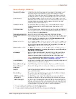
Modem Settings (Device Ports)
Note:
Depending on the
State
and
Mode
you select, different fields are available.
DTR Control
The type of DTR control feature. The options include:
None
,
Toggle DTR
, or
Auto
Enable DTR
:
None:
No option selected.
Toggle DTR:
If enabled, when a user disconnects from a device port, DTR will be
toggled. DTR will be de-asserted, and after a 2-second delay, will be re-asserted.
This feature can be used when a serial connection requires DSR to be active for
the attached device to connect. In this case, toggling DTR will end any active
connection on the device.
Auto Enable DTR:
If enabled, DTR will be de-asserted and will remain de-
asserted until the first connection (Connect Direct, Telnet, SSH, TCP In or
ConsoleFlow Web Terminal Session) is established to the device port. At this time,
DTR will be asserted. DTR will remain asserted as long as any connection exists
to the device port. Once the last connection is terminated, DTR will be deasserted.
The Assert DTR setting is ignored if DTR Control is set to Auto Enable.
Note:
Applies to serial RJ45 device ports only.
Reverse Pinout
If enabled, swaps the positions of the serial lines, such that the direction of data or
the signal is reversed. For instance, TX is swapped with RX. Enabling Reverse
Pinout facilitates connections to Cisco and Sun style RS-45 console ports using a
straight through Ethernet patch cable, without the need for a rolled cable or
adapter. Enabled by default.
Note:
Applies to serial RJ45 device ports only. All Lantronix serial adapters are
intended to be used with Reverse Pinout disabled.
USB VBUS
For USB Device Ports only. If enabled, the USB VBUS signal provides power to
the USB device attached to a device port. Disabling VBUS will power down the
device as long as it is bus-powered instead of self-powered. The VBUS 5V signal
is up to 100 mA per port, but not to exceed 600mA total per USB I/O Module.
Drawing more than 150 mA on a USB port will shut down the VBUS 5V.
Caution:
USB ports are designed for data traffic only. They are not
designed for charging or powering devices. Over-current conditions on
VBUS 5V may disrupt operations.
State
Used if an external modem is attached to the device port. If enabling, set the
modem to dial-out, dial-in, dial-back, dial-on-demand, dial-in/host list, dial-back &
dial-on-demand, dial in & dial-on-demand, CBCP Server, and CBCP Client.
Modem Dialing States (on page 186)
information.
Mode
The format in which the data flows back and forth:
Text:
In this mode, the EMG assumes that the modem will be used for
remotely logging into the command line. Text mode can only be used for
dialing in or dialing back.
Text
is the default.
PPP:
This mode establishes an IP-based link over the modem. PPP
connections can be used in dial-out mode (e.g., the EMG unit connects to an
external network), dial-in mode (e.g., the external computer connects to the
network that the EMG is part of), or dial-on-demand.
Содержание EMG 8500
Страница 1: ...Part Number PMD 00008 Revision A October 2019 EMG Edge Management Gateway User Guide EMG 8500 ...
Страница 69: ...6 Networking EMG Edge Management Gateway User Guide 69 Figure 6 2 Network Network Settings 2 of 2 ...
Страница 302: ...14 Maintenance EMG Edge Management Gateway User Guide 302 Figure 14 12 About EMG ...

