
1. HARDWARE OVERVIEW
2. INSTALLATION
EDS3000PS Device Server Quick Start Guide
1.
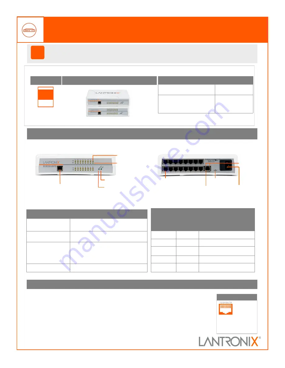
RTS
(Out)
2.
DTR
(Out)
3.
TX
(Out)
4.
GND
5.
GND
6.
RX
(In)
7.
DSR
(In)
8.
CTS
(In)
RS
-
232 Pin Assignment
!
Thank you for choosing Lantronix. Please register the EDS3000PS in order to receive notifications for
firmware and documentation updates at
www.lantronix.com/product
-
registration
.
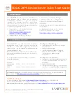
EDS3000PS
Quick Start
Accessories
Part Number
Power Cord, 125 V
AC/10 A
-
6 ft cord length
500
-
215
-
R
Networking cable, RJ45
-
DB9
Female Cable to DTE Device,
6 ft length
500
-
103
-
R
START
WHAT
’
S IN THE BOX
1.
Power off the serial device that will be connected to the EDS3000PS.
2.
Attach a RJ 45 serial cable between the EDS3000PS and your serial
device.
3.
Connect an CAT5E Ethernet cable between the EDS3000PS Ethernet
port and your Ethernet network.
4.
Connect the power cord and apply power.
5.
Power up the serial device.
EDS3008PS, EDS3016PS
Other adapters are available and are sold
separately.
LEDs
Description
Transmit (Green)
Blinking = EDS is transmitting data on the
serial port.
Receive (Orange)
Blinking = EDS is receiving data on the
serial port.
Diagnostic (Green)
Fast blink= Initial startup, loading OS.
Slow blink (once per second) = Operating
system startup.
ON = Unit has finished booting.
Power (Blue)
ON = EDS is receiving power.
Ethernet LEDs
Left LED
Right LED
Description
OFF
OFF
No Link
ON
OFF
Link 10Mbps or 100Mbps
Blinking
OFF
Activity 10Mbps or 100Mbps
ON
ON
Link 1000Mbps
Blinking
ON
Activity 1000Mbps
EDS3016PS Back View
RJ45 Serial Port
Power Connector
Reset Switch
RJ45 Ethernet Port
EDS3016PS Front View
Power LED
Transmit LED
Receive LED
Diagnostic LED
Console Port
Ethernet LEDs