


c.
The
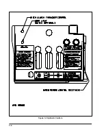
20,000 lb PNEUMATIC WINCH CON-
TROL
has two positions.
RELEASE
In this position, the winch is disen-
gaged and air tension (if present) is
released from the cable. Allow up to
15 seconds for release of air tension.
The cable can then “free-wheel”. The
cable may need to be slackened to
allow winch to disengage.
IMPORTANT
WHEN REELING WINCH, MOMENTARILY RO-
TATE REEL IN OPPOSITE DIRECTION TO RE-
LIEVE TENSION ON WINCH GEARS. THIS WILL
AID IN WINCH RELEASE.
TENSION
In this position, the winch is engaged
and cable can be “power” spooled in
or out. The winch is now controlled
by the Winch Hydraulic Lever. Winch
air tensioner will also be engaged, if
present.
d.
The
12,000 lb or 20,000 lb WINCH AIR
TENSION
or pressure on the cable is con-
trolled by an air pressure regulator located
behind the main control panel. It is set at 60
psi but can be adjusted, if desired, for more or
less tension.
1.
To adjust, turn the regulator adjusting
knob. Clockwise rotation increases and
counterclockwise rotation decreases outlet
pressure and tension.
2.
When reducing from a higher to a lower
setting, first reduce to some pressure less
than that desired, then bring up to the
desired point.
3.
Push lockring on adjusting knob downward
to lock pressure setting. To release, push
lockring upward. Free spool tension is
applied by adjustable spring load on the
cable. Free spool tension can be adjusted,
if desired, for more or less free spool
tension.
e.
Once the winch is selected, winch operation
is the same as described in
Section 3-18.1.
3-19 AIR RIDE OPERATION
3-19.1
Trailer air pressure must be maintained
above 90 PSI before operating.
PROTEC-
TION VALVES
are used to maintain 65 PSI
air brake pressure during suspension or re-
mote system air loss.
3-19.2
The semitrailer is equipped with a ride
height control valve located on rear axle.
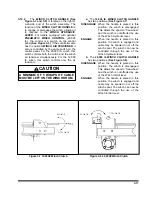
CAUTION
IF SUSPENSION AIR LOSS SHOULD
OCCUR, COMPLETELY DEFLATE SUS-
PENSION AND TEMPORARILY OPER-
ATE ON THE AIR SPRINGS INTERNAL
RUBBER BUMPERS. CAREFULLY
PROCEED TO THE NEAREST SEMI-
TRAILER SERVICE FACILITY. TO DE-
FLATE THE AIR SUSPENSION, DIS-
CONNECT THE LOWER CONNECTION
ON THE LINKAGE OF THE AUTOMATIC
AIR VALVES. ROTATE THE VALVE
CONTROL ARMS DOWN ABOUT 45o
TO EXHAUST THE AIR. TO RESTORE
TO NORMAL OPERATION, SIMPLY RE-
VERSE THE PROCEDURE.
3-18
Содержание 825A
Страница 3: ...MODEL 825A 835 DETACHABLE TRAILER OPERATOR S MANUAL PURCHASED FROM DATE ADDRESS PHONE NO SERIAL NO i...
Страница 8: ......
Страница 12: ......
Страница 14: ...3 2 Figure 3 1 Model 825 Trailer Terminology Figure 3 2 Service Hookups...
Страница 18: ...3 6 Figure 3 3 Hydraulic Controls...
Страница 22: ...3 10 Figure 3 5 Swingout Outrigger Platform Extension...
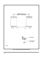
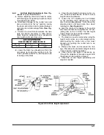
Страница 24: ...3 12 Figure 3 6 Gooseneck Attachment to Frame...
Страница 34: ......
Страница 36: ...4 2 Figure 4 1 Lubrication Points...
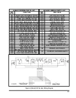
Страница 40: ...4 6 Figure 4 2 Model 825A Wiring Diagram...
Страница 43: ...4 9 Figure 4 4 Tandem Axle Air Ride Suspension System...
Страница 44: ...4 10 Figure 4 5 Tandem Axle W Flip Air Ride Suspension System...
Страница 47: ...4 13 Figure 4 8 Checking Axle Alignment Figure 4 9 Examples of Camber...
Страница 52: ...4 18 Figure 4 12 Axle and Brake Assembly...
Страница 59: ...4 25 Figure 4 18 Mounting Tires and Wheels Figure 4 19 Stud Tightening Sequence...
Страница 69: ...NOTES 5 9...
Страница 70: ......


