23
Call 1-888-370-6531 for Technical Support
6.3.3 Nozzle Line Assembly Cleaning
How often?
Annually, or if the nozzle becomes blocked with debris (indicated by a higher operating fuel
pressure at the pump-pressure gauge).
Tools Required:
½” and ¾” open end wrenches, ½” and 5/8” sockets/ratchet, 1/4 in. nut driver, hex wrench
set, vise, flat-blade screwdriver, small wire brush or pipe cleaner (from optional maintenance
accessory brush kit), parts washer fluid, rags, safety glasses, rubber gloves.
Replacement Parts:
Annual maintenance kit (PN 75000208).
Procedure:
1.
Remove the burner, following steps 1 through 4 in Section 6.4.1.
2.
Remove the elbow and straight fitting together from the side of the burner.
3.
Remove the thumb screw and open the hinged cover. NOTE: Take a picture of the assembly and
wiring before disassembling to use as a reference later.
4.
Remove the plastic air tube from the quick connect fitting in the nozzle block by pushing the metal
ring on the end of the fitting in, while pulling the tube out.
5.
Disconnect the white plug from the receptacle.
6.
Disconnect the red preheater wires, the black temperature switch wires, and the black solenoid valve
wires from the terminal block. To remove a wire, push the corresponding button of top of the
terminal block down with your finger or a screwdriver while gently tugging on the wire.
7.
Then remove the panel nut and washer from the outside of the burner. If the aluminum bulkhead
fitting spins with the nut, you will have to hold it with a second wrench inside the burner.
8.
Tilt the nozzle line assembly and pull it to the side to free the bulkhead fitting. Then slide and lift the
nozzle line assembly out of the burner through the open cover.
9.
Disassemble and clean the nozzle line assembly thoroughly. HINT: Take some pictures of the
assembly first to use as a reference later. NOTE: Take care not to submerge the electronic
components in oil or cleaning fluid.
Elbow, Straight Fitting,
Panel Nut and Washer
Содержание MX 75
Страница 2: ......
Страница 41: ...8 Appendices 8 1 Wiring Diagram ...
Страница 42: ......
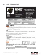
Страница 43: ...34 Call 1 888 370 6531 for Technical Support 8 2 Primary Control Instructions ...
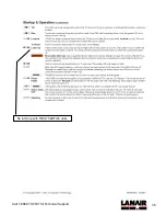
Страница 44: ...35 Call 1 888 370 6531 for Technical Support Not used with RES 75 kBTU h units ...
Страница 45: ...36 Call 1 888 370 6531 for Technical Support No latch up with RES 75 kBTU h units ...
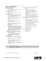
Страница 46: ...37 Call 1 888 370 6531 for Technical Support ...
Страница 54: ...45 Call 1 888 370 6531 for Technical Support 9 ...


