


119
14
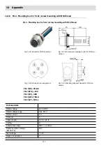
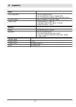
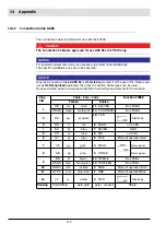
Appendix
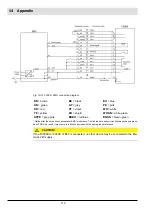
Fig. 14-31 F300K - FMS connection diagram
* Optional for the derivation of exceptional EMC interference. The link leads to a short circuit between chassis groun-
dand FPE. As a result, it may come to influence devices with the same ground reference.
CAUTION!
If the F300KUI or F300K +FB30 is connected, no other device may be connected to the Eta-
matic 24V supply.
BN
= brown
BK
= black
BU
= blue
GN
= green
GY
= grey
PK
= pink
RD
= red
VT
= violet
WH
= white
YE
= yellow
SH
= shield
WHGN
= white-green
GYPK
= grey-pink
RDBU
= red-blue
BNGN
= brown-green
Содержание F300K Series
Страница 1: ...www lamtec de Sensors and Systems for Combustion Engineering Manual F300K Compact Flame Scanner ...
Страница 2: ......
Страница 26: ...25 5 User Interface 5 2 Menu tree ...
Страница 31: ...30 6 Commissioning Marking information on the device Example F300K F300K UI FB30 Warning e g ...
Страница 46: ...45 6 Commissioning The data has now been determined and sent to the flame scanner Fig 6 21 Successful transfer ...
Страница 121: ...120 14 Appendix 14 3 EU Declaration of Conformity ...
Страница 122: ...121 14 Appendix ...
Страница 125: ...124 14 Appendix ...