


209
8
Options
NOTICE
The limits of the technical data must be strictly adhered to.
8.4
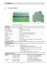
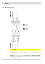
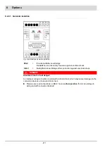
Expansion Module for LSB - LEM100
The LEM100 adds an LSB interface (CAN) to BurnerTronic. The LEM100 isolates electrically
the BT-output and the connected modules.
You must connect 24 V protective low voltage externally to the LEM and the connected mod-
ules.
If you want to connect the BurnerTronic to LSB the LEM100 is required.
If you are running BurnerTronic in combination with LCM100 already, you do not need
LEM100, because LCM100 has a LSB interface and a 24-V-power-supply integrated.
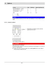
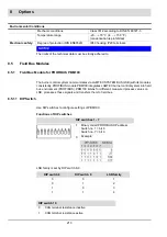
8.4.1
DIP Switch
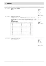
You can configure settings of LEM100 using DIP switches.
Functions of DIP switches
You can activate or deactivate the LSB terminating resistor by DIP switch 1.
DIP switches 2-3 are reserved.
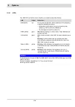
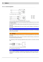
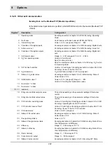
Input pulse width
min. 200 µs
Digital speed feedback input
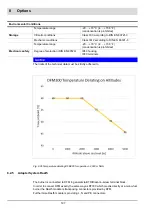
Environmental Conditions
Operation
Climatic conditions
Class 3K5 according to DIN EN 60721-3
Mechanic conditions
Class 3M5 according to DIN EN 60721-3
Temperature range
-20 ... +60 °C (-4 ... +140 °F)
(condensation is prohibited)
Transport
Climatic conditions
Class 2K3 according to DIN EN 60721-3
Mechanic conditions
Class 2M2 according to DIN EN 60721-3
Temperature range
-20 ... +70 °C (-4 ... +158 °F)
(condensation is prohibited)
Storage
Climatic conditions
Class 1K3 according to DIN EN 60721-3
Mechanic conditions
Class 1M2 according to DIN EN 60721-3
Temperature range
-20 ... +70 °C (-4 ... +158 °F)
(condensation is prohibited)
Electronic safety
Degree of protection (DIN EN60529)
IP40 housing
IP20 terminals
DIP switch 1
1
CAN-Bus activated
0
CAN-Bus deactivated
Содержание BT300 BurnerTronic
Страница 2: ......
Страница 21: ...20 3 Product Description Fig 3 3 UI300 and Fig 3 4 UI300 and dimensional drawings Fig 3 5 UI300 panel cut out...
Страница 25: ...24 3 Product Description Fig 3 9 Temperature derating BT300 for operation 2000 m NHN...
Страница 49: ...48 4 Design and Functions Fig 4 20 Oil with pilot burner BT300...
Страница 50: ...49 4 Design and Functions Fig 4 21 Oil without pilot burner BT300...
Страница 51: ...50 4 Design and Functions Fig 4 22 Gas with pilot burner and leakage test BT300...
Страница 52: ...51 4 Design and Functions Fig 4 23 Gas without pilot burner and leakage test BT300...
Страница 53: ...52 4 Design and Functions Fig 4 24 Oil without pilot burner BT335...
Страница 54: ...53 4 Design and Functions Fig 4 25 Gas without pilot burner and leakage test BT335...
Страница 59: ...58 4 Design and Functions Fig 4 28 Leakage test process diagram...
Страница 98: ...97 6 Operating Control and Displays...
Страница 99: ...98 6 Operating Control and Displays...
Страница 102: ...101 6 Operating Control and Displays NOTICE If the license agreements are not accepted the installation is aborted...
Страница 103: ...102 6 Operating Control and Displays...
Страница 105: ...104 6 Operating Control and Displays...
Страница 106: ...105 6 Operating Control and Displays...
Страница 107: ...106 6 Operating Control and Displays...
Страница 109: ...108 6 Operating Control and Displays...
Страница 126: ...125 6 Operating Control and Displays 6 3 4 2 Curve Table Fig 6 37 Curve table window...
Страница 246: ...242 10 EU Declaration of Conformity 10 EU Declaration of Conformity...
Страница 247: ...243 10 EU Declaration of Conformity...
Страница 248: ...244 10 EU Declaration of Conformity...


