


O & M Manual – Insulated Case ATS Rev: October 2020
Publication Number:
MN0100700E
Version: V10.01.20
Page 65
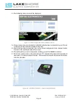
Table 21 - DSE2130 LED Indications
Function
Color
Action
Power on / Link Lost
RED
Steady when DC supply is connected, and data is being
received from the host controller.
Flashing when the DC supply is connected and the data
connection to the host controller is not operating.
ID Switch - The rotary ID switch is used to select the ‘Identification’ of the 2130 expansion
module as the host controller gives instructions to a number of 2130 expansion modules at the
same time.
Consult the relevant module’s operating instructions for further details on number of supported
expansion units.
The enclosure cover must be unclipped, and removed, to gain access to the switch. The switch
should be operated using a small screwdriver and set to match the required ID.
NOTE: The ID must be set to be a unique number, different from the ID of any other 2130 input
expansion module connected on the DSEnet. The ID of the 2130 will not interfere with the ID
of any other
type
of expansion module. For instance, it is OK to have a 2130 with ID1 and a
2157 with ID1, as the two modules are a different type of expansion board.
Table 22 - DSE2130 Fault Diagnosis
Fault Indications
Suggestion
Inputs don’t Activate on the Host Controller
Ensure the host controller is correctly
configured to accept the DSE2130
Power LED Indication Does Not Illuminate
Check polarity and size of the connected
DC supply are within the specifications of
the DSE2130
Power LED Flashes
This means the communications link to the
host controller has been lost.
Check the connection of the DSEnet paying
particular attention to the cable type being
used and the positioning of the termination
resistors.
Please contact Lake Shore Electric Technical Support if unable to resolve the expansion boards
problem.


