


O & M Manual – Insulated Case ATS Rev: October 2020
Publication Number:
MN0100700E
Version: V10.01.20
Page 64
Table 20 - Instruments
Symptom
Possible Remedy
Inaccurate S1 & S2
measurements on controller
display
Check that the CT primary, CT secondary and VT ratio settings are
correct for the application.
Check that the CTs are wired correctly with regards to the direction of
current flow (P1, P2 and S1, S2) and additionally ensure that CTs are
connected to the correct phase (errors occur if CT1 is connected to
phase 2).
Remember to consider the power factor. i.e. (kW = kV A x power factor)
The controller is true RMS measuring so gives more accurate display
when compared with an ‘averaging’ meter such as an analogue panel
meter or some lower specified digital multimeters.
Accuracy of the controller is better than 1% of full scale. i.e. S1
volts full scale is 333 V, phase-neutral, so accuracy is ±3.33 V (1%
of 333 V).
7.3.
Relay Expansion Board(s) (If Applicable)
This section will provide a brief troubleshooting guide to the possible problems with the
expansion board(s) that may be installed in the ATS. Please call the technical support line for
help for more information if needed.
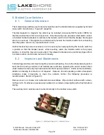
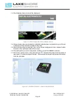
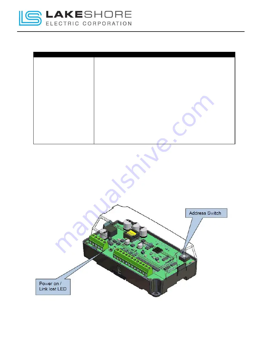
7.3.1.
DSE2130 – Input Expansion Board
Figure 47 - DSE2130 Controls and Indications