


O & M Manual – Insulated Case ATS Rev: October 2020
Publication Number:
MN0100700E
Version: V10.01.20
Page 28
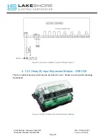
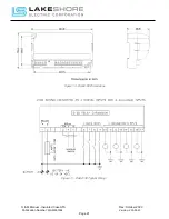
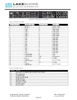
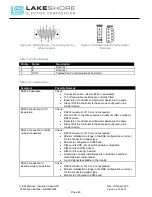
Figure 21 - Bottom PLC Terminals
Table 5 - Bottom Terminals
Terminal Number
Connection Type
Terminal Label
Description
1
Battery (-)
-
Battery (-) Input
2
Battery (+)
+
Battery (+) Input
3
Output
G
Mosfet Output
4
Output
H
Mosfet Output
5
Output
I
Mosfet Output
6
Output
J
Mosfet Output
7
Output
K
Mosfet Output
8
Output
L
Mosfet Output
9
Input
A
Mosfet Input
10
Input
B
Mosfet Input
11
Input
C
Mosfet Input
12
Input
D
Mosfet Input
13
Input
E
Mosfet Input
14
Input
F
Mosfet Input
15
Input
G
Mosfet Input
16
Input
H
Mosfet Input
17
Input
I
Mosfet Input
18
Input
J
Mosfet Input
19
Input
K
Mosfet Input
20
Input
L
Mosfet Input
21
Communication
B
Data +
22
Communication
A
Data -
23
Communication
SCR
Shield Ground
24
N/A
N/A
Not Used
25
Common
E
Form "B" Contact
26
Normally Closed
27
N/A
N/A
Not Used
28
Common
F
Form "A" Contact
29
Normally Open
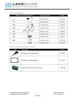
Table 6 - RS232 Pinouts
Pin No.
Notes
1
Received Line Signal Detector (Data Carrier Detect)
2
Received Data
3
Transmit Data
4
Data Terminal Ready
5
Signal Ground
6
Data Set Ready
7
Request To Send
8
Clear To Send
9
Ring Indicator


