


O & M Manual – Insulated Case ATS Rev: October 2020
Publication Number:
MN0100700E
Version: V10.01.20
Page 15
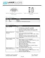
12.
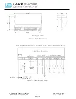
Additional Control Wire Installation:
There are numerous accessories available on Lake
Shore transfer switches which require external connections. Refer to the specific ATS
unit’s schematic and layout "XXXXXX-03 and XXXXXX-04" drawings for additional
connections which must be made.
3.2.
Placing the Transfer Switch in Operation
Before energizing the transfer switch electrically, be certain all external connections have been
properly made according to the wiring diagram provided. Revisit section 3.1 Mounting and
Connecting for reference.
Inspect all wires, cables, and bus bar for abraded insulation, foreign matter, and electrical
clearance.
The LSE8600 controller monitors the voltage source of both S1 and S2 directly to verify that the
sources are within acceptable parameters. The ATS will not operate on a voltage other than that
stamped on the nameplate of the transfer switch, so please verify the equipment received is built
for the system it is being installed within.
3.2.1.
ATS Control Start-Up
1.
Verify the DC voltage on terminals to terminals designated on the specific units schematic
drawing "XXXXXX-03" drawings is available. (Typical Terminal #’s: "010 (negative)" and
"011 (positive)”)
If correct, continue to the next step.
If DC voltage is not present, verify the DC wiring / DC power supply for errors until
the power loss cause is found.
2.
Close and lock the main door of the ATS.
3.
Place the "Control" key switch in the "Enable" position located on the door of the Automatic
Transfer Switch (ATS).
4.
The LSE8600 Controller will boot up in the
"Auto" mode.
a.
If utility power is available, then the ATS will close the "NS" switch and connect the
load to utility power.
b.
If utility power is not available, then the ATS will start the generator, close the "ES"
switch, and connect the load to generator power.
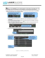
5.
Once power has been applied to the ATS load and it appears to be working properly, verify
that the unit is reading proper voltage on the LSE8600 S1 and S2 menus on the screen
display. Use the Left / Right arrows next to the
button to view the correct menu of the
source available if not already visible.
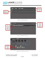
6.
Use the Up / Down arrows next to the
button to scroll through S1 or S2 power readings.