background image

21

Revo 18|36 Lathe \ Setup   

Setup

Setup Overview (MUST READ)

When setting up your Revo 18|36 Lathe, please take a moment to read this overview prior to starting.

The machine comes mostly assembled. You will have to assemble the legs, headstock, tailstock, tool
storage and the tool rest to the bed of the machine. 

NOTICE! 

It is recommended that the head stock, tool

rest and tailstock be removed from the bed of the lathe to ease assembly (Covered later in the manual).

After Setup, There may be a few adjustment to be made. All of these adjustments are done prior to shipping
the machine, but if found to need adjustments please follow the adjustment guides.


If you have any doubt about the described procedure, seek professional assistance. Do not

attempt any procedure that you feel is unsafe, or that you do not have the physical capability of achieving.

Videos

REVO 1836 Lathe Setup - Unboxing The Lathe -
Part 1

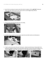
REVO 1836 Lathe Setup - 3 Inch Riser Blocks
Install - Part 2

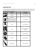
REVO 1836 Lathe Setup - Mount Legs To Bed - Part
3

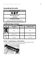
REVO 1836 Lathe Setup - Mount Head And
Tailstocks - Part 4

Содержание REVO 18

Страница 1: ...Revo 18 36 Lathe Owner s Manual MLAREVO 1836 110 150 MLAREVO 1836 220 2 19 2021 256540 PRECISION WOODWORKING...

Страница 2: ...to change specifications design or included equipment without notice or obligation No part of this publication may be reproduced transmitted or translated into any language in any form by any means wi...

Страница 3: ...ecifications 14 Machine Overview 15 Setup 21 Videos 21 Placement Unboxing 23 Inventory List 27 Assembling the Lathe 29 Standard Accessories 34 Adjustments 38 Maintenance 43 Troubleshooting 44 Wiring 4...

Страница 4: ...s relates to protecting your safety and preventing problems Safety Call outs An imminently hazardous situation which if not avoided will result in death or serious injury Sometimes displayed as A pote...

Страница 5: ...not be modified and or used for any application other than that for which it was designed If you have any questions relative to a particular application do not use the machine until you have first co...

Страница 6: ...oose clothing gloves neckties rings bracelets or other jewelry which may get caught in moving parts Nonslip footwear is recommended Wear protective hair covering to contain long hair 11 ALWAYS USE SAF...

Страница 7: ...re de travail 6 RENDEZ L ATELIER L PREUVE DES ENFANTS avec des verrous des interrupteurs principaux ou en enlevant les cl s de d marrage sur les 7 NE FORCEZ PAS L OUTIL L ou l effectuera un meilleur t...

Страница 8: ...ES ACCESSOIRES RECOMMAND S Consultez le manuel d instru pour conna tre les accessoires recommand s L u lisa on d accessoires inappropri s pose des risques de blessures aux lisateurs 18 NE VOUS TENEZ J...

Страница 9: ...ese chemicals are Lead from lead based paint Crystalline silica from bricks cement and other masonry products Arsenic and chromium from chemically treated lumber Your risk of exposure varies depending...

Страница 10: ...on the above information Variables outside of our control are Actual voltage supplied to the machine Electrical code that must be met in your local province An electrician will verify that all the dem...

Страница 11: ...ypically double that of the running amperage Most woodworking machines use this type of fuse Grounding Methods This machine must be grounded while in use to protect the operator from electric shock In...

Страница 12: ...s This tool is intended for use on a circuit that has an outlet that looks like the one illustrated in Fig A The tool has a grounding plug that looks like the plug illustrated in Fig A A temporary ada...

Страница 13: ...6 0 6 120 120 120 120 up to 25 25 50 50 100 100 150 18 AWG 16 AWG 16 AWG 14 AWG 6 10 6 10 6 10 6 10 120 120 120 120 up to 25 25 50 50 100 100 150 18 AWG 16 AWG 14 AWG 12 AWG 10 12 10 12 10 12 10 12 1...

Страница 14: ...524mm 660mm 1194mm Tool rest 12 305mm 12 305mm Speed range high 135 3500 RPM 135 3500 RPM Speed range low 50 1300 RPM 50 1300 RPM VFD DeltaS1 variable frequency drive DeltaS1 variable frequency drive...

Страница 15: ...this owner s manual in its entirety before assembly or use The lathe consists of a number of major parts which are discussed in this manual Take the time to read this section and become familiar with...

Страница 16: ...iron and their heavy construction gives the machine a low center of gravity and ensures that it is very stable The legs are supplied with adjustable feet to allow the machine to be leveled Head Stock...

Страница 17: ...other tools which have a number 2 Morse Taper The tail stock can be moved to any position on the lathe bed and locked to suit the job at hand NOTICE Lathes with machine serial number 20074159 and late...

Страница 18: ...trol system VFD is housed at the back of the head stock The VFD converts single phase 220v to three phase There is a speed readout at the front of the lathe with controls to fine adjust the RPM of the...

Страница 19: ...s Emergency stop button The emergency stop button will lock in the OFF position when fully depressed To reset it twist clockwise and it will pop out Forward reverse switch The forward reverse switch s...

Страница 20: ...rt the motor and the rotation of the spindle Speed display The speed display shows the RPM of the spindle Variable speed adjustment knob The Variable speed adjustment knob adjusts the spindle speed Tu...

Страница 21: ...y Covered later in the manual After Setup There may be a few adjustment to be made All of these adjustments are done prior to shipping the machine but if found to need adjustments please follow the ad...

Страница 22: ...836 Lathe Setup Installing The Comparator Part 7 REVO 1836 Lathe Setup Install The Vacuum Inverter Part 8 REVO 1836 Setup Install 12 Inch Swingaway Extension Part 9 REVO 1836 Lathe Setup The 20 Inch E...

Страница 23: ...ssing or damaged items NOTICE All shipping damage must be noted upon delivery and signed by the owner and the delivery driver If you find any damaged items in your package you must contact Laguna Tool...

Страница 24: ...referably one made of concrete or something similar 5 Locate it close to a power source and dust collection 6 Allow an area for the storage of blanks finished products and tools Unboxing Quick Referen...

Страница 25: ...the top packaging and remove the second leg 4 Cut all four corners with box cutter Cut the styrofoam around the headstock and the tailstock 5 There is a stop at both ends of the bed The stop is a saf...

Страница 26: ...o the bed Disengage the lock handle prior to removal NOTICE Even if you lifted the lathe out of the box with a lift please remove everything from the bed 7 Clean the grease off all components with WD4...

Страница 27: ...parts from plastic bags before laying them out to inventory them REF Description Q PACKAGING Bed 1 Lower Packaging Headstock 1 Lower Packaging TailStock NOTICE For lathes with serial number 20074159...

Страница 28: ...Upper Packaging Quill Knob 1 Upper Packaging Faceplate Wrench 1 Upper Packaging Knock Out Rod 1 Upper Packaging Adjustable Feet 4 Upper Packaging Tailstock Bracket Hardware 1 Upper Packaging Headstock...

Страница 29: ...side If you purchased the riser blocks install them now Installing the legs to the bed Parts Needed REF Description Q Installation Location Bed 1 Legs 2 Bed Adjustable Feet 4 Legs Hardware 8 Legs to...

Страница 30: ...two people will be needed to perform this step 5 Fine tune the leveling feet so the lathe bed is level Method 2 Using a Table 1 Install the Leveling feet to the legs 2 Place the bed on the table 3 Wit...

Страница 31: ...Q Installation Location Headstock 1 Bed TailStock NOTICE For lathes with serial number 20074159 and later include a new Precise Center Function on the tailstock 1 Bed 1 Tailstock Banjo 1 Bed Cleaning...

Страница 32: ...post To remedy this clean off any grease or oil with a shop rag An anti slip friction paste can be used to further hold the post The Tailstock Headstock and Banjo all use the same cam locking mechanis...

Страница 33: ...d When giving power to your machine ensure that the electrical supply corresponds with that of the machine Single phase 220V or 110V See the Electrical Safety section for all electrical information It...

Страница 34: ...iarize proper procedure Installing the Faceplate Parts Needed REF Description Q Installation Location Face Plate 1 Upper Packaging Faceplate Wrench 1 Upper Packaging There are two set screws on the fa...

Страница 35: ...he head stock is clean The drive center has a number No 2 Morse Taper that fits into the head stock Push the center into the head stock bore firmly and ensure that it is securely located To remove the...

Страница 36: ...ter into the tail stock bore firmly and ensure that it is securely located To remove the center rotate the adjusting handle until it is as far back as possible and this will eject the center Installin...

Страница 37: ...REF Description Q Installation Location Tool Rack 1 Leg The Tools rack can be installed on any of the mounting locations and in the upside down position higher NOTICE If installing in the front positi...

Страница 38: ...ng on when performing this procedure The lathe has two sets of pulleys for high 135 3500 RPM and low 50 1300 RPM speed ranges Adjust between the speed ranges as follows 1 Disconnect the electric suppl...

Страница 39: ...move between the 3 sets of holes loosen the clamp knobs and slide the indexing plunger assembly to align with the selected hole set Clamp in position with the clamp knobs Try the plunger in a few diff...

Страница 40: ...the tailstock and the bed NOTICE Only make very small adjustments and then recheck the clearance After adjustment The tailstock should be slid along the bed to check for any area that it binds in the...

Страница 41: ...tailstock casting There is clearance in the holes that allows the tailstock to be moved in relation to the slide plate The headstock also has two clamp screws but one is accessible from under the head...

Страница 42: ...ipped with a precise position function that allows you to ensure center to center contact between the spindle and quill The adjustment is simple 1 Loosen the four Allen screws by a 1 8 hex wrench 2 Lo...

Страница 43: ...ks cuts and general wear If damage is found replace the belt Bearings All bearings are sealed for life and do not require any maintenance If a bearing becomes faulty replace it Rust The lathe is made...

Страница 44: ...otor 3 Power line overloaded Correct overloaded condition 4 Low voltage Correct low voltage condition Motor overheats The motor is designed to run hot but should it overheat it has an internal thermal...

Страница 45: ...3 2 4 5 1 L2 L1 4 L2 10 5 1 L1 3 2 L1 1 4 L2 10 5 7 8 6 9 9 6 7 6 1 220V PLUG SENSOR 8 PLUG 110V 8 L1 Make sure the black pin is inserted into the correct position for either 110V or 220V pin 110V 22...

Страница 46: ...46 Revo 18 36 Lathe Replacement Parts Diagram Replacement Parts Diagram Bed Headstock Drive Center...

Страница 47: ...47 Revo 18 36 Lathe Replacement Parts Diagram Bed Banjo Tail Stock Live Center...

Страница 48: ...VO1836 113 3 Faceplate 1 14 PLAREVO1836 114 Clamp Bolt 3 15 PLAREVO1836 115 Sleeve 2 16 PLAREVO1836 116 Rubber Sleeve 2 17 PLAREVO1836 117 Knob 1 18 PLAREVO1836 118 Headstock Adjusting Plate 1 19 PLAR...

Страница 49: ...Stop Bolt 3 50 PLAREVO1836 150 Tool Caddy 1 51 PLAREVO1836 151 Knockout Rod 1 52 PLAREVO1836 152 Braking Resistor Cord 1 53 PLAREVO1836 153 Lock Handle 1 54 PLAREVO1836 154 Control Box 1 55 PLAREVO183...

Страница 50: ...er 6205 1 85 PLAREVO1836 185 Key 6x6x30 2 86 PLAREVO1836 186 Key 8x7x25 1 87 PLAREVO1836 187 Key 8x7x60 1 88 PLAREVO1836 188 E Ring E19 2 89 PLAREVO1836 189 E Ring E15 4 90 PLAREVO1836 190 E Ring E5 1...

Страница 51: ...9 PLAREVO1836 1119 Set Screw 1 4 20UNCx3 8 1 120 PLAREVO1836 1120 Socket Head Button Screw M8x30 1 121 PLAREVO1836 1121 Socket Head Button Screw M8x45 1 122 PLAREVO1836 1122 Socket Head Cap Screw 5 16...

Страница 52: ...3 8 16UNCx1 1 4 2 149 PLAREVO1836 1149 Tailstock Bracket 1 150 PLAREVO1836 1150 Socket Head Cap Screw 3 8 16UNCx3 4 2 151 PLAREVO1836 1151 Magnet 1 152 PLAREVO1836 1152 Screw M4x6 2 153 PLAREVO1836 1...

Страница 53: ...original purchaser must present the original receipt as proof of purchase Shipping Damage Laguna Tools and the purchasing customer is not responsible for damage or loss caused by a freight company or...

Страница 54: ...Carolina 825 Bistline Dr Ste 101 West Columbia SC 29172 U S A Phone 1 800 234 1976 Minnesota 5250 West 74th St Edina MN 55439 U S A Phone 1 949 474 1200 LAGUNA AMERICAN HEADQUARTERS LAGUNA EUROPE Walk...

Отзывы: