104
Maximizer Maintenance
5.
While a helper is operating the Maximizer by pulling down the corresponding lever (see Figure
1) and is holding it in this position to let the pressure build up (the Maximizer is at the end of
the front stroke), adjust the screw to set the correct forward pressure on the gauge at 2000 psi.
N
OTE
:
Backward pressure is used to move the Maximizer panel toward the tailgate; forward pressure
is used to move the Maximizer panel toward the front bulkhead.
N
OTE
:
Turn the adjustment screw clockwise to increase pressure or counter-clockwise to reduce it.
6.
Once the correct pressure has been set, tighten the adjustment screw locknut.
Replacing the Maximizer Cylinder
If you detect potential problems with the Maximizer cylinder, you might have to remove it and
replace it.
Also, if the Maximizer panel needs to be removed and replaced, you will have to remove the cylinder
too.
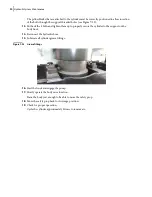
Removing the Cylinder Guard
You need to remove the cylinder guard first in order to remove the Maximizer cylinder.
N
OTE
:
2 people are required to carry out this procedure.
To remove the cylinder guard, apply the following procedure:
1.
Ensure that the parking brake is applied.
2.
Start the engine.
3.
Engage the hydraulic pump.
4.
Open the tailgate and set the tailgate safety prop.
5.
Fully move the Maximizer towards the front bulkhead to clear the cylinder guard.
6.
Turn OFF the hydraulic pump and stop the engine.
7.
Apply the Lockout/Tagout procedure (see
8.
Use a zip cutter to cut through the tacks lined along the cylinder guard.
9.
Remove the guard once all the tacks have been cut.
Apply the Lockout/Tagout procedure at all times when maintenance or inspection is
carried out on the vehicle.
DANGER!
Содержание Top Select
Страница 1: ...TOP SELECT TM MAINTENANCE MANUAL...
Страница 2: ......
Страница 3: ...TOP SELECT MAINTENANCE MANUAL...
Страница 8: ...vi Table of Contents...
Страница 34: ...26 Safety...
Страница 40: ...32 General Cleanliness...
Страница 72: ...64 Loading Container Maintenance...
Страница 104: ...96 Preventive Maintenance...
Страница 121: ...Lubrication 113 Figure 11 2 Body hinges Grease Fittings on Body Figure 11 3 Tailgate and hooks...
Страница 122: ...114 Lubrication Figure 11 4 Partition Figure 11 5 Optional Maximizer Location of lube zerks...
Страница 123: ...Lubrication 115 Figure 11 6 Roof hinges and loading cylinders...
Страница 124: ...116 Lubrication Figure 11 7 Lube chart...
Страница 132: ...124 Troubleshooting...
Страница 134: ...126 Hydraulic and Pneumatic Circuit Diagrams Hydraulic Schematics Single Side Bucket...
Страница 135: ...Hydraulic and Pneumatic Circuit Diagrams 127 Single Side Bucket w Maximizer...
Страница 136: ...128 Hydraulic and Pneumatic Circuit Diagrams Dual Side Bucket...
Страница 137: ...Hydraulic and Pneumatic Circuit Diagrams 129 Dual Side Bucket w Maximizer...
Страница 138: ...130 Hydraulic and Pneumatic Circuit Diagrams Dual Side Bucket w Maximizer and Dual Tailgate Cylinder...
Страница 139: ...Hydraulic and Pneumatic Circuit Diagrams 131 Air System Schematics TS 1000 w Options...
Страница 140: ...132 Hydraulic and Pneumatic Circuit Diagrams TS 2000 w Options...


