General Maintenance
159
a) Start the engine and engage the hydraulic pump.
b) Retract the cylinder using the outside chute-operating lever/button.
c) Turn OFF the hydraulic pump and stop the engine.
d) Lock out and tag out the vehicle (see
Locking Out and Tagging Out the Vehicle
page 14).
9 j.
Remove the plate under the pillow block (see Figure 3
223).
Two bolts hold this part in place.
9 k.
Unscrew the greasing hose from its attachment on the pillow block (see Figure 3
223).
9 l.
Remove the pillow block.
Two ½” bolts located under the pillow block hold this part in place (see Figure 3
224).
Figure 3
-
224 Bolts holding pillow block in
The rear section of the chute shaft is now free and unattached.
Next: Disconnecting the front section of the chute shaft.
9 m.
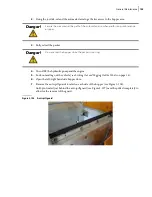
Proceed with the removal of both floating panels (see Figure 3
225).
Danger!
Never enter the hopper while the hydraulic system is engaged.
Warning!
Beware of the floating panel pinch points. Keep your fingers and hands away from them.
Содержание EXPERT
Страница 1: ...EXPERT TM MAINTENANCE MANUAL...
Страница 2: ......
Страница 3: ...EXPERT MAINTENANCE MANUAL...
Страница 10: ...viii Table of Contents...
Страница 18: ...8 Introduction...
Страница 244: ...234 General Maintenance...
Страница 251: ...Lubrication 241 Figure 4 11 Glass compartment lubrication chart optional...
Страница 252: ...242 Lubrication Figure 4 12 EXPERT lubrication chart...
Страница 261: ...Lubrication 251 Figure 4 27 Packer lubrication points 2 Grease fitting LH side front cylinder pin...
Страница 263: ...Lubrication 253 Pump Drive Shaft U Joint Figure 4 30 Pump drive shaft lubrication points Grease fittings...
Страница 264: ...254 Lubrication...
Страница 320: ...310 Hydraulic System...
Страница 357: ...Troubleshooting 349...
Страница 358: ...350 Troubleshooting...
Страница 386: ...378 Multiplexing...
Страница 388: ...380 Lifting Arms Figure 10 1 Mounting bolts Figure 10 2 Wear pads Figure 10 3 Helping Hand gripper...


