5 7
5 7
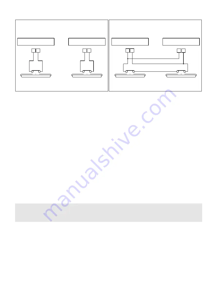
MASTER ACTUATOR
SLAVE ACTUATOR
SEPARATE STOPPING OF WINGS ON DETECTION BY
OPENING SAFETY SENSOR
SIMULTANEOUS STOPPING OF WINGS ON DETECTION
BY CLOSING SAFETY SENSOR
“MASTER”
WING SENSOR
“SLAVE”
WING SENSOR
“MASTER”
WING SENSOR
“SLAVE”
WING SENSOR
5 7
5 7
5 7
MASTER ACTUATOR
SLAVE ACTUATOR
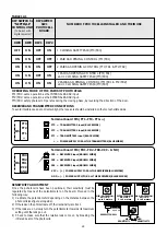
Fig. 4
31
13.1.1) ACTUATOR WITH MASTER CONTROL UNIT
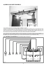
Make the electrical connections to the MASTER control unit as described in sect. 1 of this manual, considering that all the control
and safety inputs (from terminal 1 to terminal 11) are activated on the MASTER actuator. When it comes to the
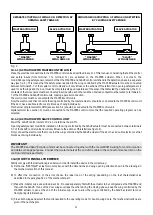
mod.SSS1opening safety sensor, remember that the MASTER and SLAVE control units handle the detection phase in a separate
way (see fig. 4). This means that the safety sensor applied to the wing controlled by the MASTER actuator must be connected
between terminals 5-7 of the master control unit and will only influence the actions of this latter. If an opening safety sensor is
used for both wings and the door must be completely stopped regardless of the sensor that detected the obstruction, the N.C.
contacts of the two sensors must be connected in series with each other and the obtained contact must be routed to terminals 5-
7 of the MASTER and SLAVE control units, making a parallel connection.
The electro-lock must be connected to the MASTER control unit.
Only the electro-lock that concerns the wing controlled by the master actuator should be connected to the MASTER control unit
if the door has a double electro-lock to block each wing individually.
Mechanical program selector SMN (see section 5.2) should be connected to the MASTER control unit.
digital selector (see section 9) must be connected to the MASTER control unit so that the required operating program can be
selected.
13.1.2) ACTUATOR WITH SLAVE CONTROL UNIT
Power the SLAVE control unit at 230V a.c. via terminal board M1.
Opening safety sensor mod.SSS1 installed on the wing controlled by the SLAVE actuator must be connected between terminals
5-7 of the SLAVE control unit and will only influence the actions of this latter (see figure 4).
Only connect the electro-lock that concerns the wing controlled by the SLAVE actuator if the door has a double electro-lock that
blocks each wing individually.
IMPORTANT!
The MASTER and SLAVE control units must be connected together with the mod.WR3MS wiring for communication
and data exchange purposes. Connect the two terminals at the end of the cable to the connectors marked J13 on the
control units (logic part LGN).
13.2) HOW TO INSTALL THE DEVICE
Strictly comply with the instructions given below in order to install the device in the correct way:
A) Fix the two "NEPTIS/LE” actuators in compliance with the dimensions and wing opening direction shown in the drawings in
the mechanical section of this manual.
B) To effect the connection of the arms choose the ideal load of the spring depending on the leaf characteristics as
described in the paragraph 8.0 of the mechanical part.
C) Make the initial set-up as described in sect. 4. Proceed separately, first with the actuator to be configured as the MASTER and
then with the SLAVE. If one of the door wings overlaps the other during the closing phase, keep the wing controlled by the
MASTER actuator open at the end of the initial set-up so as to allow the wing controlled by the SLAVE actuator to move
freely during its initial set-up.
D) Close both wings and select the functions suited to the operating mode for double-wing doors. The relative instructions are
given in the next chapter.
Содержание NEPTIS/LE
Страница 4: ...MECHANICAL SECTION NEPTIS LE 550 110 120 Nepti N e p t i S ...
Страница 14: ...notes ...
Страница 15: ...ELECTRONIC SECTION NEPTIS LE Nepti N e p t i S ...
Страница 38: ...notes ...
Страница 39: ......

