


48
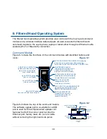
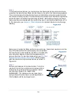
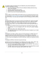
5.0 INCHES
FRONT PANEL
HEADER
CORNER
POST
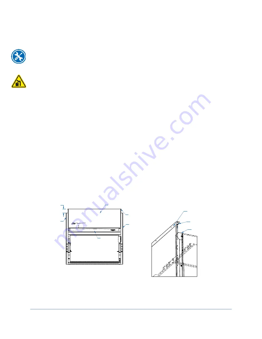
CORNER
POST
PANEL'S
LOCATORS
CORNER
POST
PANEL'S
LOCATORS
FRONT PANEL
Front Panel Removal
Removal of the front panel is necessary for changing the filtration technology.
Tools Required:
6 FT ladder
It is recommended to utilize at least two (2) persons to remove the front panel,
particularly for a 6 FT and 8 FT model. The front panel is tall and heavy. Use safe lifting
practices, and to set the panel where it cannot fall over while uninstalled from the
filtered hood.
Removal of the front panel can be done by following these steps:
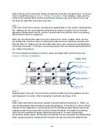
1. Place ladder up by the front of the filtered hood. Climb ladder and inspect the
front panel. Make sure there is nothing that will get caught by the panel during
the removal process. See Figure 8-1.
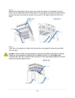
2. When you are sure there are no obstructions, lift the panel up vertically about 5
inches. This will ensure the locators holding the panel in place will have
clearance over the corner posts. See Figure 8-2.
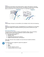
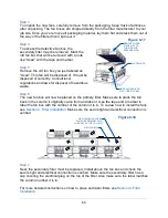
3. When free of the corner posts, the front panel should be lowered from its spot in
the top front of the filtered hood to a person standing beside the ladder.
4. With the panel at a normal floor level height, the panel can be stored out of the
way.
To reinstall the front panel, follow the steps 1 through 4 in reverse.
Figure 8-2
Figure 8-1
Содержание Protector Airo
Страница 78: ...78 Fans and Lights not working ...
Страница 79: ...79 Vertical sash no longer operates smoothly ...
Страница 80: ...80 Electrical duplex outlets no longer have power Fan operates but lights dim or not working ...
Страница 81: ...81 Contaminates outside the filtered hood ...
Страница 82: ...82 Lights operate but fans will not ...
Страница 83: ...83 Smart Command Alarms ...
Страница 84: ...84 If needed contact Labconco to troubleshoot further ...
Страница 88: ...88 1 2 3 4 5 6 7 8 9 10 13 12 11 14 15 19 22 23 24 26 25 27 28 20 18 REFERENCE SERIAL TAG Figure A 1 ...
Страница 94: ...94 Wiring Diagram Figure C 1 ...
Страница 109: ...109 Figure E 5 TYPICAL NEUTRODINE FILTRATION TECHNOLOGY 12 SCREWS CORNER POST FRONT PANEL HEADER ...